Putting it all together
In the vertex input section we created a buffer named vertex_buffer which
contains the shape of our triangle, and wrote the source code of a vertex shader that positions
vertices on the image.
In the fragment shader section we wrote the source code of a fragment shader that fills pixels with a color.
Finally in the render passes section we create a render pass and a framebuffer that contains the target image.
It is now time to put everything together and perform the draw operation!
Note: You can find the full source code of this chapter here.
Creating a graphics pipeline
Just like we had to create a compute pipeline in order to perform a compute operation, we have to create a graphics pipeline before we perform a draw operation.
This is done by first creating the shaders, just like for a compute pipeline:
#![allow(unused)]
fn main() {
mod vs {
    vulkano_shaders::shader!{
        ty: "vertex",
        src: r"
            #version 460

            layout(location = 0) in vec2 position;

            void main() {
                gl_Position = vec4(position, 0.0, 1.0);
            }
        ",
    }
}

mod fs {
    vulkano_shaders::shader!{
        ty: "fragment",
        src: "
            #version 460

            layout(location = 0) out vec4 f_color;

            void main() {
                f_color = vec4(1.0, 0.0, 0.0, 1.0);
            }
        ",
    }
}

let vs = vs::load(device.clone()).expect("failed to create shader module");
let fs = fs::load(device.clone()).expect("failed to create shader module");
}
Then we can create the graphics pipeline.
#![allow(unused)]
fn main() {
use vulkano::pipeline::graphics::input_assembly::InputAssemblyState;
use vulkano::pipeline::graphics::vertex_input::Vertex;
use vulkano::pipeline::graphics::viewport::{Viewport, ViewportState};
use vulkano::pipeline::GraphicsPipeline;
use vulkano::render_pass::Subpass;

// More on this latter.
let viewport = Viewport {
    offset: [0.0, 0.0],
    extent: [1024.0, 1024.0],
    depth_range: 0.0..=1.0,
};

let pipeline = {
    // A Vulkan shader can in theory contain multiple entry points, so we have to specify
    // which one.
    let vs = vs.entry_point("main").unwrap();
    let fs = fs.entry_point("main").unwrap();

    let vertex_input_state = MyVertex::per_vertex()
        .definition(&vs.info().input_interface)
        .unwrap();

    let stages = [
        PipelineShaderStageCreateInfo::new(vs),
        PipelineShaderStageCreateInfo::new(fs),
    ];

    let layout = PipelineLayout::new(
        device.clone(),
        PipelineDescriptorSetLayoutCreateInfo::from_stages(&stages)
            .into_pipeline_layout_create_info(device.clone())
            .unwrap(),
    )
    .unwrap();

    let subpass = Subpass::from(render_pass.clone(), 0).unwrap();

    GraphicsPipeline::new(
        device.clone(),
        None,
        GraphicsPipelineCreateInfo {
            // The stages of our pipeline, we have vertex and fragment stages.
            stages: stages.into_iter().collect(),
            // Describes the layout of the vertex input and how should it behave.
            vertex_input_state: Some(vertex_input_state),
            // Indicate the type of the primitives (the default is a list of triangles).
            input_assembly_state: Some(InputAssemblyState::default()),
            // Set the fixed viewport.
            viewport_state: Some(ViewportState {
                viewports: [viewport].into_iter().collect(),
                ..Default::default()
            }),
            // Ignore these for now.
            rasterization_state: Some(RasterizationState::default()),
            multisample_state: Some(MultisampleState::default()),
            color_blend_state: Some(ColorBlendState::with_attachment_states(
                subpass.num_color_attachments(),
                ColorBlendAttachmentState::default(),
            )),
            // This graphics pipeline object concerns the first pass of the render pass.
            subpass: Some(subpass.into()),
            ..GraphicsPipelineCreateInfo::layout(layout)
        },
    )
    .unwrap()
};
}
When we draw, we have the possibility to draw only to a specific rectangle of the screen called a
viewport. The borders of the viewport will map to the -1.0 and 1.0 logical coordinates
that we covered in the vertex input section of the book. Any part of the
shape that ends up outside of this rectangle will be discarded.
We configured the pipeline so that we use one specific viewport, and that the state of this viewport is fixed. It is possible to specify dynamic states when creating the pipeline, but since we left those at the default which is empty, there are none. This makes it not possible to change the viewport for each draw command, but adds more performance. Because we are drawing only one image and not changing the viewport between draws, this is the optimal approach. If you wanted to draw to another image of a different size, you would have to create a new pipeline object. Another approach would be to use a dynamic viewport, where you would pass your viewport in the command buffer instead.
Note: If you configure multiple viewports, you can use geometry shaders to choose which viewport the shape is going to be drawn to. This topic isn't covered here.
Drawing
Now that we have all the ingredients, it is time to bind everything and insert a draw call inside of our render pass.
To draw the triangle, we need to pass the pipeline, the vertex_buffer and the actual draw command:
#![allow(unused)]
fn main() {
let mut builder = AutoCommandBufferBuilder::primary(
    &command_buffer_allocator,
    queue.queue_family_index(),
    CommandBufferUsage::OneTimeSubmit,
)
.unwrap();

builder
    .begin_render_pass(
        RenderPassBeginInfo {
            clear_values: vec![Some([0.0, 0.0, 1.0, 1.0].into())],
            ..RenderPassBeginInfo::framebuffer(framebuffer.clone())
        },
        SubpassBeginInfo {
            contents: SubpassContents::Inline,
            ..Default::default()
        },
    )
    .unwrap()

    // new stuff
    .bind_pipeline_graphics(pipeline.clone())
    .unwrap()
    .bind_vertex_buffers(0, vertex_buffer.clone())
    .unwrap()
    .draw(
        3, 1, 0, 0, // 3 is the number of vertices, 1 is the number of instances
    )
    .unwrap()

    .end_render_pass(SubpassEndInfo::default())
    .unwrap()

// (continued below)
}
The first parameter of the .draw() method is the number of vertices of our shape. All the other
constants are in the case of drawing on multiple viewports or drawing multiple objects with
instancing (we won't cover that here).
Note: If you wanted to draw multiple objects, the most straight-forward method is to call
draw()multiple time in a row.
Once we have finished drawing, let's do the same thing as in the mandelbrot example and write the image to a PNG file.
To do that, as before, let's first create the buffer:
#![allow(unused)]
fn main() {
// crop

let buf = Buffer::from_iter(
    memory_allocator.clone(),
    BufferCreateInfo {
        usage: BufferUsage::TRANSFER_DST,
        ..Default::default()
    },
    AllocationCreateInfo {
        memory_type_filter: MemoryTypeFilter::PREFER_HOST
            | MemoryTypeFilter::HOST_RANDOM_ACCESS,
        ..Default::default()
    },
    (0..1024 * 1024 * 4).map(|_| 0u8),
)
.expect("failed to create buffer");

// crop
}
And then write the rest of the operations:
#![allow(unused)]
fn main() {
    .copy_image_to_buffer(CopyImageToBufferInfo::image_buffer(image, buf.clone()))
    .unwrap();

let command_buffer = builder.build().unwrap();

let future = sync::now(device.clone())
    .then_execute(queue.clone(), command_buffer)
    .unwrap()
    .then_signal_fence_and_flush()
    .unwrap();
future.wait(None).unwrap();

let buffer_content = buf.read().unwrap();
let image = ImageBuffer::<Rgba<u8>, _>::from_raw(1024, 1024, &buffer_content[..]).unwrap();
image.save("image.png").unwrap();

println!("Everything succeeded!");
}
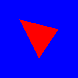
And here is what you should get:
Next: Windowing