Safe Rust wrapper around the Vulkan API
Vulkano is a Rust wrapper around the Vulkan graphics API. It follows the Rust philosophy, which is that as long as you don't use unsafe code you shouldn't be able to trigger any undefined behavior. In the case of Vulkan, this means that non-unsafe code should always conform to valid API usage.
What does vulkano do?
- Provides a low-levelish API around Vulkan. It doesn't hide what it does but provides some comfort types.
- Plans to prevent all invalid API usages, even the most obscure ones. The purpose of Vulkano is not to simply let you draw a teapot, but to cover all possible usages of Vulkan and detect all the possible problems in order to write robust programs. Invalid API usage is prevented thanks to both compile-time checks and runtime checks.
- Can handle synchronization on the GPU side for you (unless you choose to do that yourself), as this aspect of Vulkan is both annoying to handle and error-prone. Dependencies between submissions are automatically detected, and semaphores are managed automatically. The behavior of the library can be customized thanks to unsafe trait implementations.
- Tries to be convenient to use. Nobody is going to use a library that requires you to browse the documentation for hours for every single operation.
![]()

![]()
![]()


Introduction
Welcome to the vulkano book! This guide will cover the basics of Vulkan and vulkano, and will help you get started with interfacing with a GPU.
It will teach you the basics of graphics programming in the sense that you will know how to draw objects on the screen. However, this book doesn't cover actual graphics programming techniques, such as loading a 3D model or adding realistic lighting to a scene. At this point, the examples in the book are very basic, but we will be adding more comprehensive tutorials in the future.
We will assume that you are familiar with the Rust programming language. If you are not, you should definitely learn it first!
An excellent way to learn is to read examples. On top of this book, you should familiarize yourself with vulkano examples. To view the current release's examples you'll need to switch to a version tag. On the branch dropdown click the tags tab. There you'll find all released versions. Master branch will contain examples that are updated continuously to match changes that are unreleased. You should only use the master branch if you are using vulkano as a git dependency.
To contribute to this book, you can create a pull request at vulkano-book repository.
Quick glossary
When you create a program (either in Rust or any other programming language) and run it, the program's instructions are executed by the CPU (Central Processing Unit).
But some computers also usually have a video card plugged in them. This video card has its own microprocessor called the GPU (Graphics Processing Unit) or the graphics processor. It can be seen more or less as a secondary machine within your main machine. Your monitor is generally plugged in to your video card if you have one.
Vulkan is a standard API whose version 1.0 was released in 2016 that lets you interface with the video card and the GPU of the machine your program is running on. Vulkano is a Rust library on top of Vulkan that makes it much easier and safer to use. After you have learned to use Vulkan/vulkano, you will be able to ask your GPU to perform operations and either write the result into memory (which you can then read from your Rust program), or to write the result to your monitor for you to physically see.
Setup
You may first need to set up some external dependencies as documented in the vulkano readme to avoid build failures in the future.
To get started with vulkano, add it as a project dependency to your Cargo.toml:
[dependencies]
vulkano = "0.34.0"
You may want to consider adding the following minimum optimization level to your Cargo.toml as
well. The purpose of this is to reduce performance artifacts resulting from the default debug
optimization.
[profile.dev]
opt-level = 1
Note: If you run into any issues with this book, please open an issue. If you have issues with vulkano itself, please also open an issue.
You are now ready to get started!
Initialization
Creating an instance
Before you can start utilizing the Vulkan API, the first thing to do is to create
an instance. An instance specifies the mapping between vulkano and the local Vulkan library.
As of vulkano version 0.31.0, the library needs to be explicitly specified by passing a
VulkanLibrary to the Instance constructor.
For starters, our program will be very simple, so, for now, creating an instance won't need any additional parameters, so we can create it with default configurations:
#![allow(unused)]
fn main() {
use vulkano::VulkanLibrary;
use vulkano::instance::{Instance, InstanceCreateFlags, InstanceCreateInfo};

let library = VulkanLibrary::new().expect("no local Vulkan library/DLL");
let instance = Instance::new(
    library,
    InstanceCreateInfo {
        flags: InstanceCreateFlags::ENUMERATE_PORTABILITY,
        ..Default::default()
    },
)
.expect("failed to create instance");
}
Like many other functions in vulkano, creating an instance returns a Result. If Vulkan is not
available on the system, this result will contain an error. For the sake of this example we call
expect on the Result, which prints a message to stderr and terminates the application if it
contains an error. In a real game or application you should handle that situation in a nicer way,
for example by opening a dialog box with an explanation. This is out of scope of this book.
The InstanceCreateFlags::ENUMERATE_PORTABILITY flag is set to support devices, such as those on
MacOS and iOS systems, that do not fully conform to the Vulkan Specification. For more details, consult the
instance documentation.
Before going further you can try your code by running:
cargo run
Enumerating physical devices
The machine you run your program on may have multiple devices that support Vulkan. Before we can ask a video card to perform some operations, we have to enumerate all the physical devices that support Vulkan and choose which one we are going to use for this operation.
In reality a physical device can be a dedicated graphics card, but also an integrated graphics processor or a software implementation. It can be basically anything that allows running Vulkan operations.
As of the writing of this book, it is not yet possible to use multiple devices simultaneously in an efficient way (eg. SLI/Crossfire). You can use multiple devices simultaneously in the same program, but there is not much point in doing so because you cannot share anything between them. Consequently the best thing to do in practice is to choose one physical device which is going to run everything:
#![allow(unused)]
fn main() {
let physical_device = instance
    .enumerate_physical_devices()
    .expect("could not enumerate devices")
    .next()
    .expect("no devices available");
}
The enumerate_physical_devices function returns a Result of an iterator to the list of
available physical devices. We call next on it to return the first device, if any. Note that the
first device is not necessarily the best device. In a real program you probably want to leave the
choice to the user (later we will see a better implementation of this).
Keep in mind that the list of physical devices can be empty. This happens if Vulkan is installed on the system, but none of the physical devices of the machine are capable of supporting Vulkan. In a real-world application you are encouraged to handle this situation properly as well.
Next: Device creation
Device creation
In the previous section we created an instance and chose a physical device from this instance.
But initialization isn't finished yet. Before being able to do anything, we have to create a device. A device is an object that represents an open channel of communication with a physical device, and it is probably the most important object of the Vulkan API.
About queues
Just like how it's possible to use multiple threads in your program running on the CPU, it's also possible to run multiple operations in parallel on the GPU of your graphics card. The Vulkan equivalent of a CPU thread is a queue. Queues are grouped by queue families.
The queue families of a physical device can be enumerated like this:
#![allow(unused)]
fn main() {
for family in physical_device.queue_family_properties() {
    println!("Found a queue family with {:?} queue(s)", family.queue_count);
}
}
While some implementations only provide one family with one queue, some others have three or four families with up to sixteen queues in some of these families.
Note: If you want to get a more precise idea of the queue families provided by the various Vulkan implementations, you can go to vulkan.gpuinfo.org, click on the report you want, and open the "Queue families" tab.
Whenever we want the device to perform an operation, we have to submit this operation to a specific queue. Some queues support only graphical operations, some others support only compute operations, and some others support both.
Creating a device
The reason why queues are relevant right now is in order to create a device, we have to tell the Vulkan implementation which type of queues we want to use. Queues are grouped into queue families, which describe their capabilities. Let's locate a queue family that supports graphical operations:
#![allow(unused)]
fn main() {
use vulkano::device::QueueFlags;

let queue_family_index = physical_device
    .queue_family_properties()
    .iter()
    .position(|queue_family_properties| {
        queue_family_properties.queue_flags.contains(QueueFlags::GRAPHICS)
    })
    .expect("couldn't find a graphical queue family") as u32;
}
Once we have the index of a viable queue family, we can use it to create the device:
#![allow(unused)]
fn main() {
use vulkano::device::{Device, DeviceCreateInfo, QueueCreateInfo};

let (device, mut queues) = Device::new(
    physical_device,
    DeviceCreateInfo {
        // here we pass the desired queue family to use by index
        queue_create_infos: vec![QueueCreateInfo {
            queue_family_index,
            ..Default::default()
        }],
        ..Default::default()
    },
)
.expect("failed to create device");
}
Creating a device returns two things: the device itself, but also a list of queue objects that will later allow us to submit operations.
Once this function call succeeds we have an open channel of communication with a Vulkan device!
Since it is possible to request multiple queues, the queues variable returned by the function is
in fact an iterator. In this example code this iterator contains just one element, so let's
extract it:
#![allow(unused)]
fn main() {
let queue = queues.next().unwrap();
}
We now have our device and our queue, which means that we are ready to ask the GPU to perform
operations.
Next: Creating a buffer
Creating a memory allocator
Before you can create buffers in memory, you have to request (allocate) some memory first.
It turns out allocating memory
efficiently and dynamically is challenging. Luckily, in vulkano, we have several kinds of memory
allocators that we can pick from depending on our use case. Since we don't have any special needs,
we can use the StandardMemoryAllocator
with default settings, that kind of allocator is general-purpose and will be your go-to option in
most cases.
#![allow(unused)]
fn main() {
use vulkano::memory::allocator::StandardMemoryAllocator;

let memory_allocator = Arc::new(StandardMemoryAllocator::new_default(device.clone()));
}
Since device is actually an Arc<Device>, the call to .clone() only clones the Arc
which isn't expensive. You should get used to passing the device as a parameter, as you will
need to do so for most of the Vulkan objects that you create. We encapsulate the memory allocator
with an atomic reference counter since Buffer::from_data requires an Arc.
Creating a buffer
When using Vulkan, you will very often need the GPU to read or write data in memory. In fact there isn't much point in using the GPU otherwise, as there is nothing you can do with the results of its work except write them to memory.
In order for the GPU to be able to access some data (either for reading, writing or both), we first need to create a buffer object and put the data in it.
Memory type filter
A Vulkan implementation might (and most often does) have multiple memory types, each being best suited to certain tasks. There are many possible arrangements of memory types a Vulkan implementation might have, and picking the right one is important to ensure most optimal performance.
When allocating memory for a buffer in vulkano, you have to provide a memory type filter,
which tells the memory allocator which memory types it should prefer, and which ones it should
avoid, when picking the right one. For example, if you want to continuously upload data to the GPU,
you should use MemoryTypeFilter::PREFER_DEVICE | MemoryTypeFilter::HOST_SEQUENTIAL_WRITE; on the
other hand, if you have some data that will largely remain visible only to the GPU, using
MemoryTypeFilter::PREFER_DEVICE brings increased performance at the cost of more complicated
data access from the CPU. For staging buffers, you should use
MemoryTypeFilter::PREFER_HOST | MemoryTypeFilter::HOST_SEQUENTIAL_WRITE.
The simplest way to create a buffer is to create it in CPU-accessible memory, by using
MemoryTypeFilter::HOST_SEQUENTIAL_WRITE or MemoryTypeFilter::HOST_RANDOM_ACCESS, together with
one of the other filters depending of whether host or device-local memory is preferred.
#![allow(unused)]
fn main() {
use vulkano::buffer::{Buffer, BufferCreateInfo, BufferUsage};
use vulkano::memory::allocator::{AllocationCreateInfo, MemoryTypeFilter};

let data: i32 = 12;
let buffer = Buffer::from_data(
    memory_allocator.clone(),
    BufferCreateInfo {
        usage: BufferUsage::UNIFORM_BUFFER,
        ..Default::default()
    },
    AllocationCreateInfo {
        memory_type_filter: MemoryTypeFilter::PREFER_DEVICE
            | MemoryTypeFilter::HOST_SEQUENTIAL_WRITE,
        ..Default::default()
    },
    data,
)
.expect("failed to create buffer");
}
We have to indicate several things when creating the buffer. The first parameter is an Arc of the
memory allocator to use.
The second parameter is the create info for the buffer. The only field that you have to override is the usage for which we are creating the buffer for, which can help the implementation perform some optimizations. Trying to use a buffer in a way that wasn't indicated when creating it will result in an error. For the sake of the example, we just create a buffer that supports being used as a uniform buffer.
The third parameter is the create info for the allocation. The field of interest is the memory
type filter.
When creating a CPU-accessible buffer, you will most commonly use
MemoryTypeFilter::PREFER_HOST | MemoryTypeFilter::HOST_SEQUENTIAL_WRITE, but in cases
where the application is writing data through this buffer continuously, using
MemoryTypeFilter::PREFER_HOST | MemoryTypeFilter::HOST_RANDOM_ACCESS is preferred as it may
yield some performance gain. Using MemoryTypeFilter::PREFER_DEVICE will get you a buffer that
is inaccessible from the CPU when such a memory type exists. Therefore, you can't use this memory
usage together with Buffer::from_data directly, and instead have to create a staging buffer
whose content is then copied to the device-local buffer.
Finally, the fourth parameter is the content of the buffer. Here we create a buffer that contains
a single integer with the value 12.
Note: In a real application you shouldn't create buffers with only 4 bytes of data. Although buffers aren't expensive, you should try to group as much related data as you can in the same buffer.
From_data and from_iter
In the example above we create a buffer that contains the value 12, which is of type i32,
but you can put any type you want in a buffer, there is no restriction. In order to give our
arbitrary types a representation that can be used in a generic way, we use the crate bytemuck
and its "plain old data" trait, AnyBitPattern. Thus, any crate which exposes types with
bytemuck support can be used in a buffer. You can also derive AnyBitPattern for you own types,
or use the vulkano-provided BufferContents derive macro:
#![allow(unused)]
fn main() {
use vulkano::buffer::BufferContents;

#[derive(BufferContents)]
#[repr(C)]
struct MyStruct {
    a: u32,
    b: u32,
}

let data = MyStruct { a: 5, b: 69 };

let buffer = Buffer::from_data(
    memory_allocator.clone(),
    BufferCreateInfo {
        usage: BufferUsage::UNIFORM_BUFFER,
        ..Default::default()
    },
    AllocationCreateInfo {
        memory_type_filter: MemoryTypeFilter::PREFER_DEVICE
            | MemoryTypeFilter::HOST_SEQUENTIAL_WRITE,
        ..Default::default()
    },
    data,
)
.unwrap();
}
While it is sometimes useful to use a buffer that contains a single struct, in practice it is very
common to put an array of values inside a buffer. You can, for example, put an array of fifty
i32s in a buffer with the Buffer::from_data function.
However, in practice it is also very common to not know the size of the array at compile-time. In
order to handle this, Buffer provides a from_iter constructor that takes an iterator to the
data as the last parameter, instead of the data itself.
In the example below, we create a buffer that contains the value 5 of type u8, 128 times. The
type of the content of the buffer is [u8], which, in Rust, represents an array of u8s whose
size is only known at runtime.
#![allow(unused)]
fn main() {
let iter = (0..128).map(|_| 5u8);
let buffer = Buffer::from_iter(
    memory_allocator.clone(),
    BufferCreateInfo {
        usage: BufferUsage::UNIFORM_BUFFER,
        ..Default::default()
    },
    AllocationCreateInfo {
        memory_type_filter: MemoryTypeFilter::PREFER_DEVICE
            | MemoryTypeFilter::HOST_SEQUENTIAL_WRITE,
        ..Default::default()
    },
    iter,
)
.unwrap();
}
Reading and writing the contents of a buffer
Once a CPU-accessible buffer is created, you can access its content with the read() or write()
methods. Using read() will grant you shared access to the content of the buffer, and using
write() will grant you exclusive access. This is similar to using a RwLock.
For example if buffer contains a MyStruct (see above):
#![allow(unused)]
fn main() {
let mut content = buffer.write().unwrap();
// `content` implements `DerefMut` whose target is of type `MyStruct` (the content of the buffer)
content.a *= 2;
content.b = 9;
}
Alternatively, suppose that the content of buffer is of type [u8] (like with the example that
uses from_iter):
#![allow(unused)]
fn main() {
let mut content = buffer.write().unwrap();
// this time `content` derefs to `[u8]`
content[12] = 83;
content[7] = 3;
}
Just like the constructors, keep in mind that being able to read/write the content of the buffer like this is specific to buffer allocated in CPU-accessible memory. Device-local buffers cannot be accessed in this way.
Next: Example operation
Example operation
Now that we are familiar with devices, queues, and buffers, we are going to see how to ask the GPU to actually do something.
What we are going to ask in this example is very simple: we will ask it to copy data from one buffer to another.
Note: You can find the full source code of this chapter here.
Creating the buffers
The first step is to create two CPU-accessible buffers: the source and the destination. This was covered in the previous section.
#![allow(unused)]
fn main() {
let source_content = 0..64;
let source = Buffer::from_iter(
    memory_allocator.clone(),
    BufferCreateInfo {
        usage: BufferUsage::TRANSFER_SRC,
        ..Default::default()
    },
    AllocationCreateInfo {
        memory_type_filter: MemoryTypeFilter::PREFER_HOST
            | MemoryTypeFilter::HOST_SEQUENTIAL_WRITE,
        ..Default::default()
    },
    source_content,
)
.expect("failed to create source buffer");

let destination_content = (0..64).map(|_| 0);
let destination = Buffer::from_iter(
    memory_allocator.clone(),
    BufferCreateInfo {
        usage: BufferUsage::TRANSFER_DST,
        ..Default::default()
    },
    AllocationCreateInfo {
        memory_type_filter: MemoryTypeFilter::PREFER_HOST
            | MemoryTypeFilter::HOST_RANDOM_ACCESS,
        ..Default::default()
    },
    destination_content,
)
.expect("failed to create destination buffer");
}
The iterators might look a bit tricky. The source_content iterator produces 64 values ranging
from 0 to 63. The destination_content iterator produces 64 values that are all equal to 0.
In other words, once created the source buffer contains sixty-four values ranging from 0 to 63
while the destination buffer contains sixty-four 0s.
Creating a command buffer allocator
Just like buffers, you need an allocator to allocate several command buffers, but you cannot use a memory allocator. You have to use a command buffer allocator. In this case we just use the standard one.
#![allow(unused)]
fn main() {
use vulkano::command_buffer::allocator::{
    StandardCommandBufferAllocator, StandardCommandBufferAllocatorCreateInfo,
};

let command_buffer_allocator = StandardCommandBufferAllocator::new(
    device.clone(),
    StandardCommandBufferAllocatorCreateInfo::default(),
);
}
Creating command buffers
In order to ask the GPU to perform an operation, we need to create a type of object that we haven't covered yet, the command buffer.
With Vulkan and vulkano you can't just execute commands one by one, as it would be too inefficient. Instead, we need to build a command buffer that contains a list of commands that we want to execute.
You can create many command buffers and use them at different times during the program. They can have different uses and can do many things. In this case, we are just going to create for the operation we are trying to achieve.
Vulkan supports primary and secondary command buffers. Primary command buffers can be sent directly to the GPU while secondary command buffers allow you to store functionality that you can reuse multiple times in primary command buffers. We won't cover secondary command buffers here, but you can read more about them.
Note: Submitting a command to the GPU can take up to several hundred microseconds, which is why we submit as many things as we can at once. OpenGL (Vulkan's predecessor) allows you to execute commands one by one, but in reality implementations buffer commands internally into command buffers. In other words, OpenGL automatically does what Vulkan requires us to do manually. In practice, OpenGL's automatic buffering often causes more harm than good in performance-critical applications.
We are going to submit the commands to the GPU, so let's create a primary command buffer:
#![allow(unused)]
fn main() {
use vulkano::command_buffer::{AutoCommandBufferBuilder, CommandBufferUsage, CopyBufferInfo};

let mut builder = AutoCommandBufferBuilder::primary(
    &command_buffer_allocator,
    queue_family_index,
    CommandBufferUsage::OneTimeSubmit,
)
.unwrap();

builder
    .copy_buffer(CopyBufferInfo::buffers(source.clone(), destination.clone()))
    .unwrap();

let command_buffer = builder.build().unwrap();
}
As you can see, it is very straight-forward. We create a builder, add a copy command to it with
copy_buffer, then turn that builder into an actual command buffer with .build(). Like we saw in
the buffers creation section, we call .clone() multiple times, but we
only clone Arcs.
One thing to notice is that the AutoCommandBufferBuilder::primary() method takes as parameter a
queue family index. This identifies the queue family that the command buffer is going to run on.
In this example we don't have much choice anyway (as we only use one queue and thus one queue
family), but when you design a real program you have to be aware of this requirement.
Submission and synchronization
The last step is to actually send the command buffer and execute it in the GPU. We can do that by synchronizing with the GPU, then executing the command buffer:
#![allow(unused)]
fn main() {
use vulkano::sync::{self, GpuFuture};

sync::now(device.clone())
    .then_execute(queue.clone(), command_buffer)
    .unwrap()
    .flush()
    .unwrap();
}
No function in vulkano immediately sends an operation to the GPU (except some unsafe low-level
functions). Instead, sync::now() creates a new type of object called a future, that keeps
alive all the resources that will be used by the GPU and represents the execution in time of the
actual operations.
The future returned by sync::now() is in a pending state and makes it possible to append the
execution of other command buffers and operations. Only by calling .flush() are these operations
all submitted at once, and they actually start executing on the GPU.
Using objects like this lets us build dependencies between operations and makes it possible to make an operation start only after a previous one is finished, while reducing the number of slow communication operations between the CPU and the GPU.
After submitting the command buffer, we might be tempted to try to read the content of the
destination buffer as demonstrated in the previous section.
However, because the CPU and GPU are now executing in parallel, calling destination.read()
now may sometimes return an error because the buffer could still be in use by the GPU.
In order to read the content of destination and make sure that our copy succeeded, we need to
wait until the operation is complete. To do that, we need to program the GPU to send back a special
signal that will make us know it has finished. This kind of signal is called a fence, and it lets
us know whenever the GPU has reached a certain point of execution.
To do that, let's actually save the future from the above example and wait for the operations to finish:
#![allow(unused)]
fn main() {
let future = sync::now(device.clone())
    .then_execute(queue.clone(), command_buffer)
    .unwrap()
    .then_signal_fence_and_flush() // same as signal fence, and then flush
    .unwrap();
}
Signaling a fence returns a future object called
FenceSignalFuture,
that has a special method .wait():
#![allow(unused)]
fn main() {
future.wait(None).unwrap();  // None is an optional timeout
}
Only after this is done can we safely call destination.read() and check that our copy succeeded.
#![allow(unused)]
fn main() {
let src_content = source.read().unwrap();
let destination_content = destination.read().unwrap();
assert_eq!(&*src_content, &*destination_content);

println!("Everything succeeded!");
}
Next: Introduction to compute operations
Introduction to compute operations
Before we go further, we need to understand the difference between a CPU and a GPU. As a reminder, the CPU is what executes your Rust program, while the GPU is what we are trying to interface with.
Both the CPU and the GPU execute instructions one by one. The instructions available for regular programs that run on the CPU include, for example, modifying a value in memory, or performing some mathematical operation.
The instructions that a GPU can execute are often limited, but they can operate on a lot of data at once. You can, for example, instruct the GPU to multiply thirty-two values by a constant, in approximately the same time that a CPU would take to multiply a single value by that constant (ignoring the overhead of transferring data between the two devices).
This is what makes GPUs very good at parallel computations which require executing the same sequence of operation on multiple values. While a CPU would perform this sequence on each value one by one, a GPU can perform it on multiple values at once.
Note: See also SIMD.
Note: In a previous section we talked about queues. These queues are usually foremost software queues, and not actual hardware constructs.
Note: You can find the full source code of this chapter here.
Usability
Vulkan (or any other API) doesn't let you directly control the threading aspect of the GPU. In order to perform an operation with multiple values at once, you will only need to indicate the list of operations to perform on one value. The Vulkan implementation will automatically make the necessary adjustments to make your operation run on multiple values at once.
This makes using a GPU much easier than if you had to manually control everything. However, you still need to be aware that your program will run multiple times in parallel, because it has consequences on what you can do without causing data races.
Example in this book
For the purpose of this book, we are going to do something very simple: we are going to multiply 65536 values by the constant 12. Even though this doesn't serve any purpose, it is a good starting point example. Most real-world usages of the GPU involve complex mathematical algorithms, and thus are not really appropriate for a tutorial.
As explained above, you don't need to use any for loop or anything similar of that sort. All we
have to do is write the operation that is performed on one value, and ask the GPU to execute
it 65536 times. Our operation here is therefore simply (in pseudo-code):
// `index` will range from 0 to 65536
buffer_content[index] *= 12;
While it may look like this code multiplies a single value by 12, in reality the Vulkan implementation will automatically handle all the details that make it possible to run this in parallel multiple times in the most optimized way.
As a preliminary action we are going to create the buffer that will contain the values. This is similar to what we already did twice:
#![allow(unused)]
fn main() {
let data_iter = 0..65536u32;
let data_buffer = Buffer::from_iter(
    memory_allocator.clone(),
    BufferCreateInfo {
        usage: BufferUsage::STORAGE_BUFFER,
        ..Default::default()
    },
    AllocationCreateInfo {
        memory_type_filter: MemoryTypeFilter::PREFER_DEVICE
            | MemoryTypeFilter::HOST_SEQUENTIAL_WRITE,
        ..Default::default()
    },
    data_iter,
)
.expect("failed to create buffer");
}
The data_buffer buffer now contains the data before the transformation, and we are going to
perform the calculation on each element.
Although notice that we're using STORAGE_BUFFER usage this time, since the buffer will be used
in the compute shader.
The next section of the book will indicate how to actually code this operation.
Compute pipelines
In order to ask the GPU to perform an operation, we have to write some kind of code for it, like we would for a regular program. A program that runs on the GPU is called a shader.
This is done in two steps:
- First we write the source code of the program in a programming language called GLSL. Vulkano will compile the GLSL code at compile-time into an intermediate representation called SPIR-V.
- At runtime, we pass this SPIR-V to the Vulkan implementation (GPU driver), which in turn converts it into its own implementation-specific format.
Note: In the very far future it may be possible to write shaders in Rust, or in a domain specific language that resembles Rust.
The GLSL code
But first, we need to write the source code of the operation. The GLSL language looks a lot like the C programming language, but has some differences.
This book is not going to cover teaching you GLSL, as it is an entire programming language. As with many programming languages, the easiest way to learn GLSL is by looking at examples.
Let's take a look at some GLSL that takes each element of a buffer and multiplies it by 12:
#version 460

layout(local_size_x = 64, local_size_y = 1, local_size_z = 1) in;

layout(set = 0, binding = 0) buffer Data {
    uint data[];
} buf;

void main() {
    uint idx = gl_GlobalInvocationID.x;
    buf.data[idx] *= 12;
}
Let's break it down a bit.
#version 460
The first line indicates which version of GLSL to use. Since GLSL was already the shading language of the OpenGL API (Vulkan's predecessor), we are in fact already at the version 4.60 of the language. You should always include this line at the start of every shader.
Note: You can use an older version for compatibility with older GPUs and Vulkan implementations.
layout(local_size_x = 64, local_size_y = 1, local_size_z = 1) in;
We want to invoke the compute shader 65536 times in total, once for each element in the buffer. But in practice we are going to ask the GPU to spawn 1024 work groups, where each work group has a local size of 64. This line of code declares what the local size is. Each element of the local size corresponds to one invocation of the shader, which gives us 1024 * 64 = 65536 invocations.
You should always try to aim for a local size of at least 32 to 64. While we could ask to spawn 65536 work groups with a local size of 1, in practice this has been benchmarked to be slower than using a larger local size.
For convenience, the number of work groups and the local size are three-dimensional. You can use
the y and z coordinates if you access a two-dimensional or a three-dimensional data structure.
The shader will be called once for each possible combination of values for x, y and z.
layout(set = 0, binding = 0) buffer Data {
    uint data[];
} buf;
This declares a descriptor, which we are going to cover in more details in the next
section. In particular, we declare a buffer whose name is buf and that
we are going to access in our code.
The content of the buffer is an unsized array of uints. A uint is always similar to a u32
in Rust. In other words the line uint data[]; is equivalent in Rust to a variable named data
of type [u32].
void main() {
Every GLSL code has an entry point named main, similar to C or Rust. This is the function that
is going to be invoked 65536 times.
uint idx = gl_GlobalInvocationID.x;
As explained above we are going to spawn 1024 work groups, each having a local size of 64. Compute
shaders in GLSL have access to several read-only static variables that let us know the index of
the invocation we are currently in. The gl_GlobalInvocationID.x value here will contain a value
that ranges between 0 and 65535. We are going to use it to determine which element of the array
to modify.
buf.data[idx] *= 12;
The content of the buffer is accessed with buf.data. We multiply the value at the given index
with 12.
Note: You can easily trigger a data race by calling, for example,
buf.data[0] *= 12;, as all of the shader invocations will access the buffer simultaneously. This is a safety problem that vulkano doesn't detect or handle yet. Doing so will lead to an undefined result, but not in an undefined behavior.
Embedding the GLSL code in the Rust code
Now that we've written the shader in GLSL, we're going to be compiling the shaders at
application compile-time. We'll accomplish this using vulkano-shaders
which is a procedural macro that manages the compile-time compilation of GLSL into SPIR-V
and generation of associated rust code.
To use vulkano-shaders, we first have to add a dependency:
# Notice that it uses the same version as vulkano
vulkano-shaders = "0.34.0"
Note:
vulkano-shadersuses the crateshaderc-sysfor the actual GLSL compilation step. When you build your project, an attempt will be made to automatically install shaderc if you don't already have it. shaderc also comes in the Vulkan SDK). See shaderc-sys crate for installation instructions should the automatic system fail.
Here is the syntax:
#![allow(unused)]
fn main() {
mod cs {
    vulkano_shaders::shader!{
        ty: "compute",
        src: r"
            #version 460

            layout(local_size_x = 64, local_size_y = 1, local_size_z = 1) in;

            layout(set = 0, binding = 0) buffer Data {
                uint data[];
            } buf;

            void main() {
                uint idx = gl_GlobalInvocationID.x;
                buf.data[idx] *= 12;
            }
        ",
    }
}
}
As you can see, we specify some "fields" in the vulkano_shaders::shader! macro to specify our
shader. The macro will then compile the GLSL code (outputting compilation errors if any) and
generate several structs and methods, including one named load. This is the method that we have
to use next:
#![allow(unused)]
fn main() {
let shader = cs::load(device.clone()).expect("failed to create shader module");
}
This feeds the shader to the Vulkan implementation. The last step to perform at runtime is to create a compute pipeline object from that shader. This is the object that actually describes the compute operation that we are going to perform. Before we can create any kind of pipeline, we need to create a pipeline layout, which most notably describes what kinds of resources will be bound to the pipeline. We are going to let vulkano auto-generate this layout for us by using shader reflection.
Note: Auto-generated pipeline layouts are great for starting out or quick prototyping, but are oftentimes suboptimal. You might be able to optimize better by creating one by hand.
#![allow(unused)]
fn main() {
use vulkano::pipeline::compute::ComputePipelineCreateInfo;
use vulkano::pipeline::layout::PipelineDescriptorSetLayoutCreateInfo;
use vulkano::pipeline::{ComputePipeline, PipelineLayout, PipelineShaderStageCreateInfo};

let cs = shader.entry_point("main").unwrap();
let stage = PipelineShaderStageCreateInfo::new(cs);
let layout = PipelineLayout::new(
    device.clone(),
    PipelineDescriptorSetLayoutCreateInfo::from_stages([&stage])
        .into_pipeline_layout_create_info(device.clone())
        .unwrap(),
)
.unwrap();

let compute_pipeline = ComputePipeline::new(
    device.clone(),
    None,
    ComputePipelineCreateInfo::stage_layout(stage, layout),
)
.expect("failed to create compute pipeline");
}
Before invoking that compute pipeline, we need to bind a buffer to it. This is covered by the next section.
Descriptor sets
In the GLSL code of the previous section, the buffer accessed by the shader was declared like this:
layout(set = 0, binding = 0) buffer Data {
    uint data[];
} buf;
In Vulkan, the buffers that a compute pipeline needs to access must be bound to what are called descriptors. The code above declares such a descriptor.
Note: A descriptor can contain a buffer, but also other types that we haven't covered yet: a buffer view, an image, a sampled image, etc. One or more descriptors of the same type can form an array.
A descriptor or array of descriptors is assigned to a binding, and bindings are grouped into
descriptor sets. The layout(set = 0, binding = 0) attribute in the
GLSL code indicates that this descriptor is assigned to binding 0 in the set 0. Binding indices
and set indices are 0-based.
What we declared in the GLSL code is actually not a descriptor set, but only a slot for a descriptor set. Before we can invoke the compute pipeline, we first need to bind an actual descriptor set to that slot.
Creating a descriptor set
Just like for buffers and command buffers, we also need an allocator for descriptor sets.
For our application, we are going to use a PersistentDescriptorSet. When creating this descriptor
set, we attach to it the result buffer wrapped in a WriteDescriptorSet. This object will describe
how will the buffer be written:
#![allow(unused)]
fn main() {
use vulkano::pipeline::Pipeline;
use vulkano::descriptor_set::{PersistentDescriptorSet, WriteDescriptorSet};
use vulkano::descriptor_set::allocator::StandardDescriptorSetAllocator;

let descriptor_set_allocator =
    StandardDescriptorSetAllocator::new(device.clone(), Default::default());
let pipeline_layout = compute_pipeline.layout();
let descriptor_set_layouts = pipeline_layout.set_layouts();

let descriptor_set_layout_index = 0;
let descriptor_set_layout = descriptor_set_layouts
    .get(descriptor_set_layout_index)
    .unwrap();
let descriptor_set = PersistentDescriptorSet::new(
    &descriptor_set_allocator,
    descriptor_set_layout.clone(),
    [WriteDescriptorSet::buffer(0, data_buffer.clone())], // 0 is the binding
    [],
)
.unwrap();
}
In order to create a descriptor set, you'll need to know the layout that it is targeting. We do
this by using the "Pipeline" trait and calling .layout() on our pipeline to obtain the pipeline's
layout. Next we'll fetch the layout specific to the pass that we want to target by using
.set_layouts().get(0) where zero indicates the first index of the pass that we are targeting.
Once you have created a descriptor set, you may also use it with other pipelines, as long as the bindings' types match those the pipelines' shaders expect. But Vulkan requires that you provide a pipeline whenever you create a descriptor set; you cannot create one independently of any particular pipeline.
We then bind each descriptor one by one in order, which here is just the buf variable. Just like
for compute_pipeline, cloning data_buffer only clones an Arc and isn't expensive.
Note:
data_bufferwas created in the introduction.
Now that we have a compute pipeline and a descriptor set to bind to it, we can start our operation. This is covered in the next section.
Dispatch
Now that we have all the needed ingredients, we can create the command buffer that will execute our compute pipeline. This is called a dispatch operation.
Creating a command buffer is similar to the example operation in a previous section.
#![allow(unused)]
fn main() {
use vulkano::command_buffer::allocator::{
    StandardCommandBufferAllocator, StandardCommandBufferAllocatorCreateInfo,
};
use vulkano::command_buffer::{AutoCommandBufferBuilder, CommandBufferUsage};
use vulkano::pipeline::PipelineBindPoint;

let command_buffer_allocator = StandardCommandBufferAllocator::new(
    device.clone(),
    StandardCommandBufferAllocatorCreateInfo::default(),
);

let mut command_buffer_builder = AutoCommandBufferBuilder::primary(
    &command_buffer_allocator,
    queue.queue_family_index(),
    CommandBufferUsage::OneTimeSubmit,
)
.unwrap();

let work_group_counts = [1024, 1, 1];

command_buffer_builder
    .bind_pipeline_compute(compute_pipeline.clone())
    .unwrap()
    .bind_descriptor_sets(
        PipelineBindPoint::Compute,
        compute_pipeline.layout().clone(),
        descriptor_set_layout_index as u32,
        descriptor_set,
    )
    .unwrap()
    .dispatch(work_group_counts)
    .unwrap();

let command_buffer = command_buffer_builder.build().unwrap();
}
First, we bind the pipeline and then the descriptor sets, indicating the type of set, the layout and the descriptor sets we are going to use. Here the number of sets could have actually been many, in which case we would indicate our desired one with an index. Because we only have one, the index is 0.
As explained in the compute pipeline section, we want to spawn 1024
work groups. This value is indicated by the actual .dispatch() method.
Just like we already covered, we submit the command buffer:
#![allow(unused)]
fn main() {
let future = sync::now(device.clone())
    .then_execute(queue.clone(), command_buffer)
    .unwrap()
    .then_signal_fence_and_flush()
    .unwrap();
}
This just schedules the operation for execution and tells the GPU to signal when finished. We have to wait for it to complete:
#![allow(unused)]
fn main() {
future.wait(None).unwrap();
}
Once complete, we can check that the pipeline has been correctly executed:
#![allow(unused)]
fn main() {
let content = data_buffer.read().unwrap();
for (n, val) in content.iter().enumerate() {
    assert_eq!(*val, n as u32 * 12);
}

println!("Everything succeeded!");
}
Next: Creating an image
Creating an image
In the buffers creation section of the book we saw that in order for the GPU to access data we had to put it in a buffer. This is not exactly true, as there is an alternative which are images.
An image in the context of Vulkan designates a multidimensional array of pixels. There are various hardcoded formats that the pixels of an image can use.
Example: the various images used by a Vulkan-using
application, as seen from a debugger
We often use Vulkan images to store images in the common sense of the word, in which case each value of the array contains the color of the pixel. However Vulkan images can also be used to store arbitrary data (in other words, not just colors).
Note: Pixels inside images are sometimes called texels, which is short for "texture pixel". Textures are a more specialized alternative to images but that no longer exist in Vulkan. The word "texel" has been less and less used over time, but the word "texture" is still very common.
Properties of an image
While we often think of images as being two-dimensional, in the context of Vulkan they can also be one-dimensional or three-dimensional. The dimensions of an image are chosen when you create it.
Note: There are two kinds of three-dimensional images: actual three-dimensional images, and arrays of two-dimensional layers. The difference is that with the former the layers are expected to be contiguous, while for the latter you can manage layers individually as if they were separate two-dimensional images.
When you create an image you must also choose a format for its pixels. Depending on the format, the pixels of an image can have between one and four components. In other words each pixel is an array of one to four values. The four components are named, in order, R, G, B and A.
Note: If you are familiar with RGBA, it may seem obvious to you that the R component (the first) is supposed to contain the red value of the pixel, the G component (the second) is supposed to contain the green value of the pixel, and same for blue and alpha. However remember that we can store arbitrary data in this format instead of colors.
You can check the list of available formats here.
For example if you create an image with the format R8_SINT, then it will only have one component.
But with the format A2R10G10B10_SSCALED_PACK32, you have all four components. The first part of
the name of each format corresponds to the memory layout of the four components. For example with
B10G11R11_UFLOAT_PACK32, each pixel is 32 bits long where the first 10 bits is the blue component,
the next 11 bits are the green component, and the last 11 bits are the red component. Don't worry
if you are confused, as we will only use the most simple formats in this book.
Image creation
Similar to buffers, images are created by providing information about the image and allocation. However, unlike buffers, images always begin in an uninitialized state.
#![allow(unused)]
fn main() {
use vulkano::image::{Image, ImageCreateInfo, ImageType, ImageUsage};
use vulkano::format::Format;

let image = Image::new(
    memory_allocator.clone(),
    ImageCreateInfo {
        image_type: ImageType::Dim2d,
        format: Format::R8G8B8A8_UNORM,
        extent: [1024, 1024, 1],
        usage: ImageUsage::TRANSFER_DST | ImageUsage::TRANSFER_SRC,
        ..Default::default()
    },
    AllocationCreateInfo {
        memory_type_filter: MemoryTypeFilter::PREFER_DEVICE,
        ..Default::default()
    },
)
.unwrap();
}
We pass the dimensions of the image and the desired format. Just like buffers, images also need to be created with flags that describe how the image will be used, and using it in a way that wasn't specified when creating it will result in an error.
Next: Clearing an image
Clearing an image
Contrary to buffers, images have an opaque implementation-specific memory layout. What this means
is that you can't modify an image by directly writing to its memory. There is no such thing as a
CpuAccessibleImage.
Note: In reality Vulkan also allows you to create linear images, which can be modified but are much slower and are supposed to be used only in some limited situations. Vulkano doesn't support them yet.
Therefore the only way to read or write to an image is to ask the GPU to do it. This is exactly what we are going to do by asking the GPU to fill our image with a specific color. This is called clearing an image.
#![allow(unused)]
fn main() {
use vulkano::command_buffer::ClearColorImageInfo;
use vulkano::format::ClearColorValue;

let mut builder = AutoCommandBufferBuilder::primary(
    &command_buffer_allocator,
    queue.queue_family_index(),
    CommandBufferUsage::OneTimeSubmit,
)
.unwrap();

builder
    .clear_color_image(ClearColorImageInfo {
        clear_value: ClearColorValue::Float([0.0, 0.0, 1.0, 1.0]),
        ..ClearColorImageInfo::image(image.clone())
    })
    .unwrap();

let command_buffer = builder.build().unwrap();
}
Note: The function is called clearing a color image, as opposed to depth and/or stencil images which we haven't covered yet.
Normalized components
The ClearColorValue enum indicates
which color to fill the image with. Depending on the format of the image, we have to use the right
enum variant of ClearValue.
Here we pass floating-point values because the image was created with the R8G8B8A8_UNORM format.
The R8G8B8A8 part means that the four components are stored in 8 bits each, while the UNORM
suffix means "unsigned normalized". The coordinates being "normalized" means that their value in
memory (ranging between 0 and 255) is interpreted as floating point values. The in-memory value 0
is interpreted as the floating-point 0.0, and the in-memory value 255 is interpreted as the
floating-point 1.0.
With any format whose suffix is UNORM (but also SNORM and SRGB), all the operations that are
performed on the image (with the exception of memory copies) treat the image as if it contained
floating-point values. This is the reason why we pass [0.0, 0.0, 1.0, 1.0]. The values 1.0 will
in fact be stored as 255 in memory.
Next: Exporting the result
Exporting the content of an image
In the previous section we filled the image with a color.
But you may now wonder how to see the result of this operation. As explained previously, images are opaque structures whose actual layout is implementation-specific. So how do we read their content?
The answer to this question is that we have to create a buffer and ask the GPU to copy the content of the image to the buffer.
Note: You can find the full source code of this section here.
Copying from the image to the buffer
The first step is to create the buffer, as we have already covered in previous sections. The buffer
has to be large enough, otherwise the copy will result in an error. Each pixel of the image
contains four unsigned 8-bit values, and the image dimensions are 1024 by 1024 pixels. Hence why
the number of elements in the buffer is 1024 * 1024 * 4.
#![allow(unused)]
fn main() {
let buf = Buffer::from_iter(
    memory_allocator.clone(),
    BufferCreateInfo {
        usage: BufferUsage::TRANSFER_DST,
        ..Default::default()
    },
    AllocationCreateInfo {
        memory_type_filter: MemoryTypeFilter::PREFER_HOST
            | MemoryTypeFilter::HOST_RANDOM_ACCESS,
        ..Default::default()
    },
    (0..1024 * 1024 * 4).map(|_| 0u8),
)
.expect("failed to create buffer");
}
And let's modify the command buffer we created in the previous section to add the copy operation:
#![allow(unused)]
fn main() {
use vulkano::command_buffer::CopyImageToBufferInfo;

builder
    .clear_color_image(ClearColorImageInfo {
        clear_value: ClearColorValue::Float([0.0, 0.0, 1.0, 1.0]),
        ..ClearColorImageInfo::image(image.clone())
    })
    .unwrap()
    .copy_image_to_buffer(CopyImageToBufferInfo::image_buffer(
        image.clone(),
        buf.clone(),
    ))
    .unwrap();
}
Since this is a memory transfer operation, this time the image values are not interpreted as floating-point values. The memory content of the image (unsigned 8-bit values) is directly copied to the buffer.
Let's not forget to execute the command buffer and block until the operation is finished:
#![allow(unused)]
fn main() {
use vulkano::sync::{self, GpuFuture};

let future = sync::now(device.clone())
    .then_execute(queue.clone(), command_buffer)
    .unwrap()
    .then_signal_fence_and_flush()
    .unwrap();

future.wait(None).unwrap();
}
Turning the image into a PNG
Now that we have a buffer that contains our image data, we will visualize it by saving it as a PNG
file. The Rust ecosystem has a crate named image that can do this.
Let's add it to our Cargo.toml:
image = "0.24"
In this library the main type that represents an image is the ImageBuffer. It can be created
from a slice:
#![allow(unused)]
fn main() {
use image::{ImageBuffer, Rgba};

let buffer_content = buf.read().unwrap();
let image = ImageBuffer::<Rgba<u8>, _>::from_raw(1024, 1024, &buffer_content[..]).unwrap();
}
The ImageBuffer can then be saved into a PNG file:
#![allow(unused)]
fn main() {
image.save("image.png").unwrap();

println!("Everything succeeded!");
}
And that's it! When running your program, a blue image named image.png should appear.

Here it is.
This might look stupid, but think about the fact that it's the GPU that wrote the content of the image. In the next sections we will do more than just fill an image with blue, but we will continue to retrieve the image's content and write it to a PNG file.
Next: Drawing a fractal with a compute shader
Drawing a fractal with a compute shader
This section isn't going to introduce any new concept, but will show a real world example by using a compute shader to write a Mandelbrot set to an image.
Just like in the introduction to compute
pipelines, we need to write some GLSL code and
create a compute pipeline. This is done with the vulkano_shader::shader! macro, as explained in
that section. Each invocation of the main function of the shader will write one pixel.
Note: You can find the full source code of this section here.
The shader
Let's spend some time on the GLSL code of the shader, which I wrote for you:
#version 460

layout(local_size_x = 8, local_size_y = 8, local_size_z = 1) in;

layout(set = 0, binding = 0, rgba8) uniform writeonly image2D img;

void main() {
    vec2 norm_coordinates = (gl_GlobalInvocationID.xy + vec2(0.5)) / vec2(imageSize(img));
    vec2 c = (norm_coordinates - vec2(0.5)) * 2.0 - vec2(1.0, 0.0);

    vec2 z = vec2(0.0, 0.0);
    float i;
    for (i = 0.0; i < 1.0; i += 0.005) {
        z = vec2(
            z.x * z.x - z.y * z.y + c.x,
            z.y * z.x + z.x * z.y + c.y
        );

        if (length(z) > 4.0) {
            break;
        }
    }

    vec4 to_write = vec4(vec3(i), 1.0);
    imageStore(img, ivec2(gl_GlobalInvocationID.xy), to_write);
}
Let's go through this line by line:
layout(local_size_x = 8, local_size_y = 8, local_size_z = 1) in;
For better parallelization, we decided that each invocation of the shader would write a value to a
pixel of the image. As you can see, this time we use a local size of 8x8, which is two-dimensional.
We will use the value of gl_GlobalInvocationID to decide which pixel we will write.
layout(set = 0, binding = 0, rgba8) uniform writeonly image2D img;
This line declares the presence of an image that we are going to use, at the slot 0 of the descriptor set 0. As you can see we have to specify its format. Trying to use an image whose format doesn't match what is expected will result in an error.
vec2 norm_coordinates = (gl_GlobalInvocationID.xy + vec2(0.5)) / vec2(imageSize(img));
vec2 c = (norm_coordinates - vec2(0.5)) * 2.0 - vec2(1.0, 0.0);
These lines declare two variables whose type is vec2. A vec2 is equivalent to a [f32; 2]
and is usually used to store 2D coordinates. Similarly ivec4 is for example equivalent to
[i32; 4], uvec3 is equivalent to [u32; 3], and so on. The Mandelbrot set is a set of complex
numbers, so in this shader we use several vec2s to store the real and imaginary parts of the
complex numbers that we manipulate.
The purpose of these two lines is to put in the variable c the complex number that corresponds
to the pixel of the image that we modify. The pixel that we are going to write will have a color
that depends on whether or not its corresponding complex number is within the set or not.
vec2 z = vec2(0.0, 0.0);
float i;
for (i = 0.0; i < 1.0; i += 0.005) {
    z = vec2(
        z.x * z.x - z.y * z.y + c.x,
        z.y * z.x + z.x * z.y + c.y
    );

    if (length(z) > 4.0) {
        break;
    }
}
We now want to find out whether the complex number that we are manipulating (i.e. c) is within
the Mandelbrot set. The definition of the Mandelbrot set says that a number c is within the set
if the function f(z) = z² + c diverges when iterated from z = 0 (z being a complex number).
This is exactly what we do in this code. We start from z = vec2(0.0, 0.0) and iterate with a
for loop. Each iteration puts the value of the next iteration in z and checks whether it is
diverging (we consider that it is diverging if length(z) > 4.0).
Note: The
lengthfunction is a built-in function in GLSL. You can find its definition and the definitions of all the built-in functions at docs.gl.
What we have left at the end of the for loop is the i variable. If c is in the set then the
function didn't diverge, the for loop went to the end, and i will contain 1.0. Otherwise c
is not within the set and i will contain a number between 0.0 and 1.0. The closer c is to
the set, the higher i will be. Therefore the value of i is what we are going to store in our
image.
vec4 to_write = vec4(vec3(i), 1.0);
imageStore(img, ivec2(gl_GlobalInvocationID.xy), to_write);
In these two lines, vec4(..), vec3(..) and ivec2(..) are conversion functions. They convert
their parameters into respectively a vec4, a vec3 and a ivec2.
vec3(i) is a shortcut for vec3(i, i, i).
Writing the pixel of an image must be done with the imageStore function. As explained in a
previous section the content of the image is opaque and is always treated as
floating-points, even though we know that its memory contains integers.
Calling this shader
Now that the shader is written, the rest should be straight-forward. We start by creating an image, as seen before:
#![allow(unused)]
fn main() {
let image = Image::new(
    memory_allocator.clone(),
    ImageCreateInfo {
        image_type: ImageType::Dim2d,
        format: Format::R8G8B8A8_UNORM,
        extent: [1024, 1024, 1],
        usage: ImageUsage::STORAGE | ImageUsage::TRANSFER_SRC,
        ..Default::default()
    },
    AllocationCreateInfo {
        memory_type_filter: MemoryTypeFilter::PREFER_DEVICE,
        ..Default::default()
    },
)
.unwrap();
}
This time we can't just clear the image like we did earlier. To actually pass the image
to the GPU shader, we first need to create a ImageView of it. An ImageView describes where
and how the GPU should access or use the image. Here, we want a view of the entire image,
so the creation isn't very difficult:
#![allow(unused)]
fn main() {
use vulkano::image::view::ImageView;

let view = ImageView::new_default(image.clone()).unwrap();
}
Now, let's create the descriptor set by adding the image view, like we did earlier:
#![allow(unused)]
fn main() {
let layout = compute_pipeline.layout().set_layouts().get(0).unwrap();
let set = PersistentDescriptorSet::new(
    &descriptor_set_allocator,
    layout.clone(),
    [WriteDescriptorSet::image_view(0, view.clone())], // 0 is the binding
    [],
)
.unwrap();
}
Next, we can create a buffer for storing the image output:
#![allow(unused)]
fn main() {
let buf = Buffer::from_iter(
    memory_allocator.clone(),
    BufferCreateInfo {
        usage: BufferUsage::TRANSFER_DST,
        ..Default::default()
    },
    AllocationCreateInfo {
        memory_type_filter: MemoryTypeFilter::PREFER_HOST
            | MemoryTypeFilter::HOST_RANDOM_ACCESS,
        ..Default::default()
    },
    (0..1024 * 1024 * 4).map(|_| 0u8),
)
.expect("failed to create buffer");
}
The command buffer contains a dispatch command followed with a copy-image-to-buffer command:
#![allow(unused)]
fn main() {
let mut builder = AutoCommandBufferBuilder::primary(
    &command_buffer_allocator,
    queue.queue_family_index(),
    CommandBufferUsage::OneTimeSubmit,
)
.unwrap();
builder
    .bind_pipeline_compute(compute_pipeline.clone())
    .unwrap()
    .bind_descriptor_sets(
        PipelineBindPoint::Compute,
        compute_pipeline.layout().clone(),
        0,
        set,
    )
    .unwrap()
    .dispatch([1024 / 8, 1024 / 8, 1])
    .unwrap()
    .copy_image_to_buffer(CopyImageToBufferInfo::image_buffer(
        image.clone(),
        buf.clone(),
    ))
    .unwrap();

let command_buffer = builder.build().unwrap();
}
And finally just like in the previous section we execute the command buffer and export the image as a PNG file:
#![allow(unused)]
fn main() {
let future = sync::now(device.clone())
    .then_execute(queue.clone(), command_buffer)
    .unwrap()
    .then_signal_fence_and_flush()
    .unwrap();

future.wait(None).unwrap();

let buffer_content = buf.read().unwrap();
let image = ImageBuffer::<Rgba<u8>, _>::from_raw(1024, 1024, &buffer_content[..]).unwrap();
image.save("image.png").unwrap();

println!("Everything succeeded!");
}
And here is what you should get:
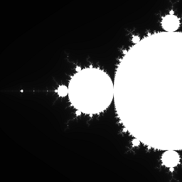
Next: Graphics pipeline introduction
Graphics pipeline introduction
Up until now, we have created command buffers that perform two kind of operations:
- Memory transfers (copying data between buffers and images, clearing an image).
- Compute operations (dispatching a compute shader).
While these two kind of operations are sufficient in order to use the power of the GPU for parallel calculations (as seen in the Mandelbrot example), there is a third kind of operations: graphical operations.
Before they were used for general-purpose calculations, GPUs were used for graphics (hence their name). To benefit from this, GPUs provide to developers a specialized well-optimized series of steps called the graphics pipeline. Using the graphics pipeline is more restrictive than using compute operations, but it is also much faster.
Note: There is nothing that the graphics pipeline can do that a compute pipeline couldn't do. However the graphics pipeline is much more specialized and therefore much more optimized. Some parts of the graphics pipeline are generally handled by dedicated chips on the hardware.
Using the graphics pipeline can look complex if you haven't done any graphics programming before, but it is essential to understand it if you want to render images in an efficient way.
Quick introduction
The purpose of the graphics pipeline is to draw a certain shape on an image. This shape can be as simple as a single triangle, or as complex as a mountain range.
In order to start a graphical operation (i.e. an operation that uses the graphics pipeline), you will need the following elements:
- A graphics pipeline object that describes the way the GPU should behave, similar to the way a compute pipeline object describes a compute operation.
- One or multiple buffers containing the shape of the object we want to draw.
- A framebuffer object, which is a collection of images to write to.
- Just like compute pipelines, we can also pass descriptor sets (and push constants, which we haven't covered yet).
When you start a graphics operation, the GPU will start by executing a vertex shader (that is part of the graphics pipeline object) on each vertex of the shape that you want to draw. This first step will allow you to position the shape on the screen.
Then the GPU finds out which pixels of the target image are covered by the shape, and executes a fragment shader (also part of the graphics pipeline object) on each of these pixels. This shader is used to determine what is the color of the shape for the given pixel is. Finally the GPU will merge this color with the color that already exists at this location.
The graphics pipeline object contains the vertex shader, the fragment shader, plus various options that allows one to further configure the behavior of the graphics card.
Note: This explanation only covers the fundamentals of graphics pipelines. Graphics pipelines have tons of configurable options, plus additional optional shader stages.
The next sections will be dedicated to covering graphics pipeline in more details.
Next: Vertex input
Vertex input
Vertex buffer
The first part of drawing an object with the graphics pipeline is to describe the shape of this object. When you think "shape", you may think of squares, circles, etc., but in graphics programming the most common shapes that one will need to work with are triangles.
Note: Tessellation shaders and alternative
PrimitiveTopologyvalues unlock the possibility to use other polygons, but this is a more advanced topic.
Each triangle is made of three vertices, and the shape of an object is just a collection of vertices linked together to form triangles. For the purpose of this book, we are only going to draw a single triangle first.
The first step to describe a shape with vulkano is to create a struct named MyVertex (the actual
name doesn't matter) whose purpose is to describe the properties of a single vertex. Once this is
done, the shape of our triangle is going to be a buffer whose content is an array of three
MyVertex objects.
#![allow(unused)]
fn main() {
use vulkano::buffer::BufferContents;
use vulkano::pipeline::graphics::vertex_input::Vertex;

#[derive(BufferContents, Vertex)]
#[repr(C)]
struct MyVertex {
    #[format(R32G32_SFLOAT)]
    position: [f32; 2],
}
}
Our struct contains a position field which we will use to store the position of the vertex on the
image we are drawing to. Being a vectorial renderer, Vulkan doesn't use coordinates in pixels.
Instead it considers that the image has a width and a height of 2 units (-1.0 to 1.0), and that the
origin is at the center of the image.
When we give positions to Vulkan, we need to use its coordinate system.
In this book we are going to draw only a single triangle for now. Let's pick a shape for it, for example this one:
Which translates into this code:
#![allow(unused)]
fn main() {
let vertex1 = MyVertex { position: [-0.5, -0.5] };
let vertex2 = MyVertex { position: [ 0.0,  0.5] };
let vertex3 = MyVertex { position: [ 0.5, -0.25] };
}
Note: The field that contains the position is named
position, but note that this name is arbitrary. We will see below how to actually pass that position to the GPU.
Now all we have to do is create a buffer that contains these three vertices. This buffer will be passed as a parameter when we start the drawing operation.
#![allow(unused)]
fn main() {
let vertex_buffer = Buffer::from_iter(
    memory_allocator.clone(),
    BufferCreateInfo {
        usage: BufferUsage::VERTEX_BUFFER,
        ..Default::default()
    },
    AllocationCreateInfo {
        memory_type_filter: MemoryTypeFilter::PREFER_DEVICE
            | MemoryTypeFilter::HOST_SEQUENTIAL_WRITE,
        ..Default::default()
    },
    vec![vertex1, vertex2, vertex3],
)
.unwrap();
}
A buffer that contains a collection of vertices is commonly named a vertex buffer. Because we
know the specific use of this buffer is for storing vertices, we specify the usage flag
VERTEX_BUFFER.
Note: Vertex buffers are not special in any way. The term vertex buffer indicates the way the programmer intends to use the buffer, and it is not a property of the buffer.
Vertex shader
At the start of the drawing operation, the GPU is going to pick each element from this buffer one by one and call a vertex shader on them.
Here is what the source code of a vertex shader looks like:
#version 460

layout(location = 0) in vec2 position;

void main() {
    gl_Position = vec4(position, 0.0, 1.0);
}
The line layout(location = 0) in vec2 position; declares that each vertex has an attribute
named position and of type vec2. This corresponds to the definition of the MyVertex struct we
created.
Note: The
Vertextrait is used to describe the attributes of an individual vertex that can be read by a vertex shader. It provides methods for specifying the format of the vertex's fields, which can be done using field attributes likeformatandnamewhen deriving the trait using theVertexderive macro.
The main function is called once for each vertex, and sets the value of the gl_Position
variable to a vec4 whose first two components are the position of the vertex.
gl_Position is a special "magic" global variable that exists only in the context of a vertex
shader and whose value must be set to the position of the vertex on the surface. This is how the
GPU knows how to position our shape.
After the vertex shader
After the vertex shader has run on each vertex, the GPU knows where our shape is located on the screen. It then proceeds to call the fragment shader.
Fragment shader
After the vertex shader has run on each vertex, the next step that the GPU performs is to determine which pixels of the target image are within the shape of the triangle. Only these pixels will be modified on the final image.
Note: More precisely, it is only if the center of a pixel is within the triangle that the GPU considers that the whole pixel is inside.
The GPU then takes each of these pixels one by one (the ones in red in the image above) and runs another type of shader named a fragment shader which we also need to provide in order to start our draw operation.
Here is what an example fragment shader looks like:
#version 460

layout(location = 0) out vec4 f_color;

void main() {
    f_color = vec4(1.0, 0.0, 0.0, 1.0);
}
The layout(location = 0) out vec4 f_color; line declares an output named f_color. Vulkan gives
you the possibility to draw to multiple images at once, which is why we need to declare each output
and its type. Drawing to multiple images at once is an advanced topic that isn't covered here.
The main() function is executed once for each pixel covered by the triangle and must write in
f_color the value that we want to write to the target image. As explained in a previous
section these values are normalized, in other words the value
1.0 will in reality write 255 in memory. In this example since our target image contains
colors, we write the color red.
Next: Render passes and framebuffers
Render passes
In order to fully optimize and parallelize command execution, we can't just ask the GPU to draw a shape whenever we want. Instead we first have to enter a special "rendering mode" by entering what is called a render pass. It is only once we have entered a render pass that you can draw.
What is a render pass?
The term "render pass" describes two things:
-
It designates the "rendering mode" we have to enter before we can add drawing commands to a command buffer.
-
It also designates a kind of object that describes this rendering mode.
Entering a render pass (as in "the rendering mode") requires passing a render pass object.
Creating a render pass
For the moment, the only thing we want to do is draw some color to a single image. This is the most simple case possible, and we only need to provide two things to a render pass: the format of the image, and the fact that we don't use multisampling (which is an anti-aliasing technique).
More complex games can use render passes in very complex ways, with multiple subpasses and multiple attachments, and with various micro-optimizations. Vulkano's API is suitable for both the simple cases and the complex usages, which is why it may look complex at first.
#![allow(unused)]
fn main() {
let render_pass = vulkano::single_pass_renderpass!(
    device.clone(),
    attachments: {
        color: {
            format: Format::R8G8B8A8_UNORM,
            samples: 1,
            load_op: Clear,
            store_op: Store,
        },
    },
    pass: {
        color: [color],
        depth_stencil: {},
    },
)
.unwrap();
}
A render pass is made of attachments and passes. Here we declare one attachment whose name
is color (the name is arbitrary), and one pass that will use color as its single output.
The load_op: Clear line indicates that we want the GPU to clear the image when entering the
render pass (i.e. fill it with a single color), while store_op: Store indicates that we want the
GPU to actually store the output of our draw commands to the image.
Note: It is possible to create temporary images whose content is only relevant inside of a render pass, in which case it is optimal to use
store_op: DontCareinstead ofstore_op: Store.
Entering the render pass
A render pass only describes the format and the way we load and store the image we are going to draw upon. It is enough to initialize all the objects we need.
But before we can draw, we also need to indicate the actual list of attachments. This is done by creating a framebuffer.
Creating a framebuffer is typically done as part of the rendering process. It is not a bad idea to keep the framebuffer objects alive between frames, but it won't kill your performance to create and destroy a few framebuffer objects during some frames.
#![allow(unused)]
fn main() {
use vulkano::render_pass::{Framebuffer, FramebufferCreateInfo};

let view = ImageView::new_default(image.clone()).unwrap();
let framebuffer = Framebuffer::new(
    render_pass.clone(),
    FramebufferCreateInfo {
        attachments: vec![view],
        ..Default::default()
    },
)
.unwrap();
}
We are now ready the enter drawing mode!
This is done by calling the begin_render_pass function on the command buffer builder.
This function takes as parameter the framebuffer, a enum, and a Vec that contains the colors
to fill the attachments with. Since we have only one single attachment, this Vec contains only
one element.
Clearing our attachment has exactly the same effect as the clear_color_image function we covered
previously, except that this time it is done by the rendering engine.
The enum passed as second parameter describes whether we are going to directly invoke draw
commands or use secondary command buffers instead. Secondary command buffers are a more advanced
topic. Be we are using only direct commands, we will leave it as ::Inline
As a demonstration, let's just enter a render pass and leave it immediately after:
#![allow(unused)]
fn main() {
use vulkano::command_buffer::{
    RenderPassBeginInfo, SubpassBeginInfo, SubpassContents, SubpassEndInfo,
};

let mut builder = AutoCommandBufferBuilder::primary(
    &command_buffer_allocator,
    queue.queue_family_index(),
    CommandBufferUsage::OneTimeSubmit,
)
.unwrap();

builder
    .begin_render_pass(
        RenderPassBeginInfo {
            clear_values: vec![Some([0.0, 0.0, 1.0, 1.0].into())],
            ..RenderPassBeginInfo::framebuffer(framebuffer.clone())
        },
        SubpassBeginInfo {
            contents: SubpassContents::Inline,
            ..Default::default()
        },
    )
    .unwrap()
    .end_render_pass(SubpassEndInfo::default())
    .unwrap();
}
The next section will introduce the draw command, which will
be inserted between begin_render_pass and end_render_pass.
Putting it all together
In the vertex input section we created a buffer named vertex_buffer which
contains the shape of our triangle, and wrote the source code of a vertex shader that positions
vertices on the image.
In the fragment shader section we wrote the source code of a fragment shader that fills pixels with a color.
Finally in the render passes section we create a render pass and a framebuffer that contains the target image.
It is now time to put everything together and perform the draw operation!
Note: You can find the full source code of this chapter here.
Creating a graphics pipeline
Just like we had to create a compute pipeline in order to perform a compute operation, we have to create a graphics pipeline before we perform a draw operation.
This is done by first creating the shaders, just like for a compute pipeline:
#![allow(unused)]
fn main() {
mod vs {
    vulkano_shaders::shader!{
        ty: "vertex",
        src: r"
            #version 460

            layout(location = 0) in vec2 position;

            void main() {
                gl_Position = vec4(position, 0.0, 1.0);
            }
        ",
    }
}

mod fs {
    vulkano_shaders::shader!{
        ty: "fragment",
        src: "
            #version 460

            layout(location = 0) out vec4 f_color;

            void main() {
                f_color = vec4(1.0, 0.0, 0.0, 1.0);
            }
        ",
    }
}

let vs = vs::load(device.clone()).expect("failed to create shader module");
let fs = fs::load(device.clone()).expect("failed to create shader module");
}
Then we can create the graphics pipeline.
#![allow(unused)]
fn main() {
use vulkano::pipeline::graphics::input_assembly::InputAssemblyState;
use vulkano::pipeline::graphics::vertex_input::Vertex;
use vulkano::pipeline::graphics::viewport::{Viewport, ViewportState};
use vulkano::pipeline::GraphicsPipeline;
use vulkano::render_pass::Subpass;

// More on this latter.
let viewport = Viewport {
    offset: [0.0, 0.0],
    extent: [1024.0, 1024.0],
    depth_range: 0.0..=1.0,
};

let pipeline = {
    // A Vulkan shader can in theory contain multiple entry points, so we have to specify
    // which one.
    let vs = vs.entry_point("main").unwrap();
    let fs = fs.entry_point("main").unwrap();

    let vertex_input_state = MyVertex::per_vertex()
        .definition(&vs.info().input_interface)
        .unwrap();

    let stages = [
        PipelineShaderStageCreateInfo::new(vs),
        PipelineShaderStageCreateInfo::new(fs),
    ];

    let layout = PipelineLayout::new(
        device.clone(),
        PipelineDescriptorSetLayoutCreateInfo::from_stages(&stages)
            .into_pipeline_layout_create_info(device.clone())
            .unwrap(),
    )
    .unwrap();

    let subpass = Subpass::from(render_pass.clone(), 0).unwrap();

    GraphicsPipeline::new(
        device.clone(),
        None,
        GraphicsPipelineCreateInfo {
            // The stages of our pipeline, we have vertex and fragment stages.
            stages: stages.into_iter().collect(),
            // Describes the layout of the vertex input and how should it behave.
            vertex_input_state: Some(vertex_input_state),
            // Indicate the type of the primitives (the default is a list of triangles).
            input_assembly_state: Some(InputAssemblyState::default()),
            // Set the fixed viewport.
            viewport_state: Some(ViewportState {
                viewports: [viewport].into_iter().collect(),
                ..Default::default()
            }),
            // Ignore these for now.
            rasterization_state: Some(RasterizationState::default()),
            multisample_state: Some(MultisampleState::default()),
            color_blend_state: Some(ColorBlendState::with_attachment_states(
                subpass.num_color_attachments(),
                ColorBlendAttachmentState::default(),
            )),
            // This graphics pipeline object concerns the first pass of the render pass.
            subpass: Some(subpass.into()),
            ..GraphicsPipelineCreateInfo::layout(layout)
        },
    )
    .unwrap()
};
}
When we draw, we have the possibility to draw only to a specific rectangle of the screen called a
viewport. The borders of the viewport will map to the -1.0 and 1.0 logical coordinates
that we covered in the vertex input section of the book. Any part of the
shape that ends up outside of this rectangle will be discarded.
We configured the pipeline so that we use one specific viewport, and that the state of this viewport is fixed. It is possible to specify dynamic states when creating the pipeline, but since we left those at the default which is empty, there are none. This makes it not possible to change the viewport for each draw command, but adds more performance. Because we are drawing only one image and not changing the viewport between draws, this is the optimal approach. If you wanted to draw to another image of a different size, you would have to create a new pipeline object. Another approach would be to use a dynamic viewport, where you would pass your viewport in the command buffer instead.
Note: If you configure multiple viewports, you can use geometry shaders to choose which viewport the shape is going to be drawn to. This topic isn't covered here.
Drawing
Now that we have all the ingredients, it is time to bind everything and insert a draw call inside of our render pass.
To draw the triangle, we need to pass the pipeline, the vertex_buffer and the actual draw command:
#![allow(unused)]
fn main() {
let mut builder = AutoCommandBufferBuilder::primary(
    &command_buffer_allocator,
    queue.queue_family_index(),
    CommandBufferUsage::OneTimeSubmit,
)
.unwrap();

builder
    .begin_render_pass(
        RenderPassBeginInfo {
            clear_values: vec![Some([0.0, 0.0, 1.0, 1.0].into())],
            ..RenderPassBeginInfo::framebuffer(framebuffer.clone())
        },
        SubpassBeginInfo {
            contents: SubpassContents::Inline,
            ..Default::default()
        },
    )
    .unwrap()

    // new stuff
    .bind_pipeline_graphics(pipeline.clone())
    .unwrap()
    .bind_vertex_buffers(0, vertex_buffer.clone())
    .unwrap()
    .draw(
        3, 1, 0, 0, // 3 is the number of vertices, 1 is the number of instances
    )
    .unwrap()

    .end_render_pass(SubpassEndInfo::default())
    .unwrap()

// (continued below)
}
The first parameter of the .draw() method is the number of vertices of our shape. All the other
constants are in the case of drawing on multiple viewports or drawing multiple objects with
instancing (we won't cover that here).
Note: If you wanted to draw multiple objects, the most straight-forward method is to call
draw()multiple time in a row.
Once we have finished drawing, let's do the same thing as in the mandelbrot example and write the image to a PNG file.
To do that, as before, let's first create the buffer:
#![allow(unused)]
fn main() {
// crop

let buf = Buffer::from_iter(
    memory_allocator.clone(),
    BufferCreateInfo {
        usage: BufferUsage::TRANSFER_DST,
        ..Default::default()
    },
    AllocationCreateInfo {
        memory_type_filter: MemoryTypeFilter::PREFER_HOST
            | MemoryTypeFilter::HOST_RANDOM_ACCESS,
        ..Default::default()
    },
    (0..1024 * 1024 * 4).map(|_| 0u8),
)
.expect("failed to create buffer");

// crop
}
And then write the rest of the operations:
#![allow(unused)]
fn main() {
    .copy_image_to_buffer(CopyImageToBufferInfo::image_buffer(image, buf.clone()))
    .unwrap();

let command_buffer = builder.build().unwrap();

let future = sync::now(device.clone())
    .then_execute(queue.clone(), command_buffer)
    .unwrap()
    .then_signal_fence_and_flush()
    .unwrap();
future.wait(None).unwrap();

let buffer_content = buf.read().unwrap();
let image = ImageBuffer::<Rgba<u8>, _>::from_raw(1024, 1024, &buffer_content[..]).unwrap();
image.save("image.png").unwrap();

println!("Everything succeeded!");
}
And here is what you should get:
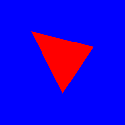
Next: Windowing
Windowing introduction
Up until now, we have only created applications that perform one quick action and then exit. What we are going to do next is create a window in order to draw graphics on it, and keep our application running forever until the window is closed.
Strictly speaking, creating a window and handling events is not covered by vulkano. Vulkano, however, is capable of rendering to window(s).
Note: You can find the full source code of this chapter here.
Creating a window
In order to create a window, we will use the winit crate.
Add to your Cargo.toml dependencies:
winit = "0.28.0"
We encourage you to browse the documentation of winit.
Because the objects that come with creating a window are not part of Vulkan itself, the first thing
that you will need to do is to enable all non-core extensions required to draw a window.
Surface::required_extensions automatically provides them for us, so the only thing left is to
pass them on to the instance creation:
#![allow(unused)]
fn main() {
use vulkano::instance::{Instance, InstanceCreateFlags, InstanceCreateInfo};
use vulkano::swapchain::Surface;
use winit::event_loop::EventLoop;

let event_loop = EventLoop::new();  // ignore this for now

let library = VulkanLibrary::new().expect("no local Vulkan library/DLL");
let required_extensions = Surface::required_extensions(&event_loop);
let instance = Instance::new(
    library,
    InstanceCreateInfo {
        flags: InstanceCreateFlags::ENUMERATE_PORTABILITY,
        enabled_extensions: required_extensions,
        ..Default::default()
    },
)
.expect("failed to create instance");
}
Now, let's create the actual window:
#![allow(unused)]
fn main() {
use winit::window::WindowBuilder;

let window = Arc::new(WindowBuilder::new().build(&event_loop).unwrap());
}
We need to wrap the Window in an Arc, so that both you and vulkano can keep a reference to it.
Next we need to create a surface, which is a cross-platform abstraction over the actual window object, that vulkano can use for rendering:
#![allow(unused)]
fn main() {
let surface = Surface::from_window(instance.clone(), window.clone());
}
After you made the change, running the program should now open a window, then immediately close it
when the main function exits.
Event handling
In order to make our application run for as long as the window is alive, we need to handle the
window's events. This is typically done after initialization, and right before the end of the
main function. Using the event_loop object:
#![allow(unused)]
fn main() {
use winit::event::{Event, WindowEvent};
use winit::event_loop::ControlFlow;

event_loop.run(|event, _, control_flow| {
    match event {
        Event::WindowEvent {
            event: WindowEvent::CloseRequested,
            ..
        } => {
            *control_flow = ControlFlow::Exit;
        },
        _ => ()
    }
});
}
What this code does is block the main thread forever, and calls the closure whenever the event loop (which we used to create our window) receives an event. These events include the events that are tied to our window, such as mouse movements.
When the user wants to close the window, a WindowEvent::CloseRequested event is received, which
makes our closure set the control_flow to ControlFlow::Exit which signals to winit that we want
an exit.
Right now, all we're doing is creating a window and keeping our program alive for as long as the window isn't closed. The next section will show how to initialize what is called a swapchain on the window's surface.
Next: Swapchain creation
Introduction to swapchains
Since we are going to draw to a window which is ultimately on the screen, things are a bit special. If you were going to write directly to the window's surface, you would introduce tearing and other strange artifacts, because you would be updating an image that's already visible on a screen. To ensure that only complete images are shown, Vulkan uses what is called a swapchain.
Note: See also the wikipedia article for a swap chain.
A swapchain is a group of one or multiple images, sometimes two images but most commonly three. If you have ever heard terms such as double buffering or triple buffering, it refers to having respectively two or three swapchain images.
The idea behind a swapchain is to draw to one of its images while another one of these images is being shown on the screen. When we are done drawing we ask the swapchain to show the image we have just drawn to, and in return the swapchain gives us drawing access to another of its images.
(Optional) Checking for swapchain support
As you may recall, previously we just selected the first physical device available:
#![allow(unused)]
fn main() {
let physical = instance
    .enumerate_physical_devices()
    .expect("could not enumerate devices")
    .next()
    .expect("no devices available");
}
However, some devices may not support swapchain creation or wouldn't be the best option. So, in this optional sub-chapter, we are going to write a simple function to filter devices for specific Vulkan extension support and select the best device. In a real application, this could be your "default" or "recommended" device, and the user could choose any other if needed.
The first step is to select all the extensions needed for your application:
#![allow(unused)]
fn main() {
use vulkano::device::DeviceExtensions;

let device_extensions = DeviceExtensions {
    khr_swapchain: true,
    ..DeviceExtensions::empty()
};
}
Next, we are going to enumerate all the devices and filter them by supported extensions:
#![allow(unused)]
fn main() {
use vulkano::device::physical::{PhysicalDevice, PhysicalDeviceType};

instance
    .enumerate_physical_devices()
    .expect("could not enumerate devices")
    .filter(|p| p.supported_extensions().contains(&device_extensions))
    // continues bellow
}
Some devices that passed the test may not have the needed queue family(ies) to present images to the surface or even support graphical operations. So, we are going to filter them and at the same time select the first queue family that is suitable:
#![allow(unused)]
fn main() {
    .filter_map(|p| {
        p.queue_family_properties()
            .iter()
            .enumerate()
            // Find the first first queue family that is suitable.
            // If none is found, `None` is returned to `filter_map`,
            // which disqualifies this physical device.
            .position(|(i, q)| {
                q.queue_flags.contains(QueueFlags::GRAPHICS)
                    && p.surface_support(i as u32, &surface).unwrap_or(false)
            })
            .map(|q| (p, q as u32))
    })
    // continues bellow
}
All the physical devices that pass the filters above are suitable for the application. However, not every device is equal, some are preferred over others. Now, we assign each physical device a score, and pick the device with the lowest ("best") score.
#![allow(unused)]
fn main() {
    .min_by_key(|(p, _)| match p.properties().device_type {
        PhysicalDeviceType::DiscreteGpu => 0,
        PhysicalDeviceType::IntegratedGpu => 1,
        PhysicalDeviceType::VirtualGpu => 2,
        PhysicalDeviceType::Cpu => 3,

        // Note that there exists `PhysicalDeviceType::Other`, however,
        // `PhysicalDeviceType` is a non-exhaustive enum. Thus, one should
        // match wildcard `_` to catch all unknown device types.
        _ => 4,
    })
    .expect("no device available");
}
In the end, your new function for selecting the best physical device should look like this:
use std::sync::Arc;

// crop
use vulkano::device::physical::{PhysicalDevice, PhysicalDeviceType};
use vulkano::device::DeviceExtensions;
use vulkano::swapchain::Surface;

fn select_physical_device(
    instance: &Arc<Instance>,
    surface: &Arc<Surface>,
    device_extensions: &DeviceExtensions,
) -> (Arc<PhysicalDevice>, u32) {
    instance
        .enumerate_physical_devices()
        .expect("could not enumerate devices")
        .filter(|p| p.supported_extensions().contains(&device_extensions))
        .filter_map(|p| {
            p.queue_family_properties()
                .iter()
                .enumerate()
                // Find the first first queue family that is suitable.
                // If none is found, `None` is returned to `filter_map`,
                // which disqualifies this physical device.
                .position(|(i, q)| {
                    q.queue_flags.contains(QueueFlags::GRAPHICS)
                        && p.surface_support(i as u32, &surface).unwrap_or(false)
                })
                .map(|q| (p, q as u32))
        })
        .min_by_key(|(p, _)| match p.properties().device_type {
            PhysicalDeviceType::DiscreteGpu => 0,
            PhysicalDeviceType::IntegratedGpu => 1,
            PhysicalDeviceType::VirtualGpu => 2,
            PhysicalDeviceType::Cpu => 3,

            // Note that there exists `PhysicalDeviceType::Other`, however,
            // `PhysicalDeviceType` is a non-exhaustive enum. Thus, one should
            // match wildcard `_` to catch all unknown device types.
            _ => 4,
        })
        .expect("no device available")
}

fn main() {
    // crop

    let device_extensions = DeviceExtensions {
        khr_swapchain: true,
        ..DeviceExtensions::empty()
    };

    let (physical_device, queue_family_index) = select_physical_device(
        &instance,
        &surface,
        &device_extensions,
    );

    // crop
}
Updating logical device creation
Now that we have our desired physical device, the next step is to create a logical device that can support the swapchain.
To do that, we need to pass all the previously required extensions:
#![allow(unused)]
fn main() {
use vulkano::device::{Device, DeviceCreateInfo, QueueCreateInfo};

let (device, mut queues) = Device::new(
    physical_device.clone(),
    DeviceCreateInfo {
        queue_create_infos: vec![QueueCreateInfo {
            queue_family_index,
            ..Default::default()
        }],
        enabled_extensions: device_extensions,
        ..Default::default()
    },
)
.expect("failed to create device");

let queue = queues.next().unwrap();
}
Creating the swapchain
Swapchains have a lot of properties: the format and dimensions of their images, an optional transformation, a presentation mode, and so on. We have to specify a value for each of these parameters when we create the swapchain. Therefore, we have to query the capabilities of the surface.
#![allow(unused)]
fn main() {
let caps = physical_device
    .surface_capabilities(&surface, Default::default())
    .expect("failed to get surface capabilities");
}
Of all of these properties, we only care about some of them, mainly the dimensions of the image (which have to be constrained between a minimum and a maximum), the behavior when it comes to transparency (composite alpha), and the format of the images.
#![allow(unused)]
fn main() {
let dimensions = window.inner_size();
let composite_alpha = caps.supported_composite_alpha.into_iter().next().unwrap();
let image_format =  physical_device
    .surface_formats(&surface, Default::default())
    .unwrap()[0]
    .0;
}
Combining everything, we can create the swapchain:
#![allow(unused)]
fn main() {
use vulkano::image::ImageUsage;
use vulkano::swapchain::{Swapchain, SwapchainCreateInfo};

let (mut swapchain, images) = Swapchain::new(
    device.clone(),
    surface.clone(),
    SwapchainCreateInfo {
        min_image_count: caps.min_image_count + 1, // How many buffers to use in the swapchain
        image_format,
        image_extent: dimensions.into(),
        image_usage: ImageUsage::COLOR_ATTACHMENT, // What the images are going to be used for
        composite_alpha,
        ..Default::default()
    },
)
.unwrap();
}
It's good to have min_image_count be at least one more than the minimal, to give a bit more
freedom to the image queue.
For additional information, check the swapchain documentation.
Next: Other initialization
Other initialization
Now that we have a swapchain to work with, let's add all the missing Vulkan objects (same as in the previous chapter example) and modify them as needed. Let's also, for clarity, move some of them to separate functions.
In the render pass, let's configure it to always use the same format as the swapchain, to avoid any invalid format errors:
#![allow(unused)]
fn main() {
fn get_render_pass(device: Arc<Device>, swapchain: &Arc<Swapchain>) -> Arc<RenderPass> {
    vulkano::single_pass_renderpass!(
        device,
        attachments: {
            color: {
                // Set the format the same as the swapchain.
                format: swapchain.image_format(),
                samples: 1,
                load_op: Clear,
                store_op: Store,
            },
        },
        pass: {
            color: [color],
            depth_stencil: {},
        },
    )
    .unwrap()
}

// main()
let render_pass = get_render_pass(device.clone(), &swapchain);
}
When we only had one image, we only needed to create one framebuffer for it. However, we now need to create a different framebuffer for each of the images:
#![allow(unused)]
fn main() {
fn get_framebuffers(
    images: &[Arc<Image>],
    render_pass: &Arc<RenderPass>,
) -> Vec<Arc<Framebuffer>> {
    images
        .iter()
        .map(|image| {
            let view = ImageView::new_default(image.clone()).unwrap();
            Framebuffer::new(
                render_pass.clone(),
                FramebufferCreateInfo {
                    attachments: vec![view],
                    ..Default::default()
                },
            )
            .unwrap()
        })
        .collect::<Vec<_>>()
}

// main()
let framebuffers = get_framebuffers(&images, &render_pass);
}
We don't need to modify anything in the shaders and the vertex buffer (we are using the same triangle), so let's just leave everything as it is, only changing the structure a bit:
#![allow(unused)]
fn main() {
#[derive(BufferContents, Vertex)]
#[repr(C)]
struct MyVertex {
    #[format(R32G32_SFLOAT)]
    position: [f32; 2],
}

mod vs {
    vulkano_shaders::shader! {
        ty: "vertex",
        src: "
            #version 460

            layout(location = 0) in vec2 position;

            void main() {
                gl_Position = vec4(position, 0.0, 1.0);
            }
        ",
    }
}

mod fs {
    vulkano_shaders::shader! {
        ty: "fragment",
        src: "
            #version 460

            layout(location = 0) out vec4 f_color;

            void main() {
                f_color = vec4(1.0, 0.0, 0.0, 1.0);
            }
        ",
    }
}
}
fn main() {
    // crop

    let vertex1 = MyVertex {
        position: [-0.5, -0.5],
    };
    let vertex2 = MyVertex {
        position: [0.0, 0.5],
    };
    let vertex3 = MyVertex {
        position: [0.5, -0.25],
    };
    let vertex_buffer = Buffer::from_iter(
        memory_allocator.clone(),
        BufferCreateInfo {
            usage: BufferUsage::VERTEX_BUFFER,
            ..Default::default()
        },
        AllocationCreateInfo {
            memory_type_filter: MemoryTypeFilter::PREFER_DEVICE
                | MemoryTypeFilter::HOST_SEQUENTIAL_WRITE,
            ..Default::default()
        },
        vec![vertex1, vertex2, vertex3],
    )
    .unwrap();

    let vs = vs::load(device.clone()).expect("failed to create shader module");
    let fs = fs::load(device.clone()).expect("failed to create shader module");

    // crop
}
As for the pipeline, let's initialize the viewport with our window dimensions:
fn get_pipeline(
    device: Arc<Device>,
    vs: Arc<ShaderModule>,
    fs: Arc<ShaderModule>,
    render_pass: Arc<RenderPass>,
    viewport: Viewport,
) -> Arc<GraphicsPipeline> {
    let vs = vs.entry_point("main").unwrap();
    let fs = fs.entry_point("main").unwrap();

    let vertex_input_state = MyVertex::per_vertex()
        .definition(&vs.info().input_interface)
        .unwrap();

    let stages = [
        PipelineShaderStageCreateInfo::new(vs),
        PipelineShaderStageCreateInfo::new(fs),
    ];

    let layout = PipelineLayout::new(
        device.clone(),
        PipelineDescriptorSetLayoutCreateInfo::from_stages(&stages)
            .into_pipeline_layout_create_info(device.clone())
            .unwrap(),
    )
    .unwrap();

    let subpass = Subpass::from(render_pass.clone(), 0).unwrap();

    GraphicsPipeline::new(
        device.clone(),
        None,
        GraphicsPipelineCreateInfo {
            stages: stages.into_iter().collect(),
            vertex_input_state: Some(vertex_input_state),
            input_assembly_state: Some(InputAssemblyState::default()),
            viewport_state: Some(ViewportState {
                viewports: [viewport].into_iter().collect(),
                ..Default::default()
            }),
            rasterization_state: Some(RasterizationState::default()),
            multisample_state: Some(MultisampleState::default()),
            color_blend_state: Some(ColorBlendState::with_attachment_states(
                subpass.num_color_attachments(),
                ColorBlendAttachmentState::default(),
            )),
            subpass: Some(subpass.into()),
            ..GraphicsPipelineCreateInfo::layout(layout)
        },
    )
    .unwrap()
}

fn main() {
    // crop

    let mut viewport = Viewport {
        offset: [0.0, 0.0],
        extent: window.inner_size().into(),
        depth_range: 0.0..=1.0,
    };

    let pipeline = get_pipeline(
        device.clone(),
        vs.clone(),
        fs.clone(),
        render_pass.clone(),
        viewport.clone(),
    );

    // crop
}
Currently the viewport state is set to fixed_scissor_irrelevant, meaning that it will be only
using one fixed viewport. Because of this, we will need to recreate the pipeline every time the
window gets resized (the viewport changes). If you expect the window to be resized many times, you
can set the pipeline viewport to a dynamic state, using
ViewportState::viewport_dynamic_scissor_irrelevant(), at a cost of a bit of performance.
Let's move now to the command buffers. In this example we are going to draw the same triangle over and over, so we can create a command buffer and call it multiple times. However, because we now also have multiple framebuffers, we will have multiple command buffers as well, one for each framebuffer. Let's put everything nicely into a function:
#![allow(unused)]
fn main() {
use vulkano::command_buffer::PrimaryAutoCommandBuffer;

fn get_command_buffers(
    command_buffer_allocator: &StandardCommandBufferAllocator,
    queue: &Arc<Queue>,
    pipeline: &Arc<GraphicsPipeline>,
    framebuffers: &Vec<Arc<Framebuffer>>,
    vertex_buffer: &Subbuffer<[MyVertex]>,
) -> Vec<Arc<PrimaryAutoCommandBuffer>> {
    framebuffers
        .iter()
        .map(|framebuffer| {
            let mut builder = AutoCommandBufferBuilder::primary(
                command_buffer_allocator,
                queue.queue_family_index(),
                // Don't forget to write the correct buffer usage.
                CommandBufferUsage::MultipleSubmit,
            )
            .unwrap();

            builder
                .begin_render_pass(
                    RenderPassBeginInfo {
                        clear_values: vec![Some([0.1, 0.1, 0.1, 1.0].into())],
                        ..RenderPassBeginInfo::framebuffer(framebuffer.clone())
                    },
                    SubpassBeginInfo {
                        contents: SubpassContents::Inline,
                        ..Default::default()
                    },
                )
                .unwrap()
                .bind_pipeline_graphics(pipeline.clone())
                .unwrap()
                .bind_vertex_buffers(0, vertex_buffer.clone())
                .unwrap()
                .draw(vertex_buffer.len() as u32, 1, 0, 0)
                .unwrap()
                .end_render_pass(SubpassEndInfo::default())
                .unwrap();

            Arc::new(builder.build().unwrap())
        })
        .collect()
}

// main()
let mut command_buffers = get_command_buffers(
    &command_buffer_allocator,
    &queue,
    &pipeline,
    &framebuffers,
    &vertex_buffer,
);
}
If you have set your pipeline to use a dynamic viewport, don't forget to then set the viewport in
the command buffers, by using .set_viewport(0, [viewport.clone()]).
In the end, the structure of your main function should look something like this:
fn main() {
    // instance

    // surface

    // physical device
    // logical device
    // queue creation

    // swapchain

    // render pass
    // framebuffers
    // vertex buffer
    // shaders
    // viewport
    // pipeline
    // command buffers

    // event loop
}
If you feel lost in all the code, feel free to take a look at full source code here.
The initialization is finally complete! Next, we will start working on the event loop and programming the functionality of each frame.
Next: Event handling
Window event handling
Now that everything is initialized, let's configure the main loop to actually draw something on the window.
First, let's match two additional events:
#![allow(unused)]
fn main() {
let mut window_resized = false;
let mut recreate_swapchain = false;

event_loop.run(move |event, _, control_flow| match event {
    Event::WindowEvent {
        event: WindowEvent::CloseRequested,
        ..
    } => {
        *control_flow = ControlFlow::Exit;
    }
    Event::WindowEvent {
        event: WindowEvent::Resized(_),
        ..
    } => {
        window_resized = true;
    }
    Event::MainEventsCleared => {}
    _ => (),
});
}
In some situations, like when the window is resized (as the images of the swapchain will no longer
match the window's) the swapchain will become invalid by itself. To continue rendering, we will
need to recreate the swapchain as well as all dependent setup. For that, we will use the
recreate_swapchain variable, and handle it before rendering.
The WindowEvent::WindowResized will be emitted when the window is, well, resized. When that
happens, we will need to recreate everything that depends on the dimensions of the window. Let's
set that in the window_resized variable, and handle it later.
As stated in the winit docs, the MainEventsCleared event "will be emitted when all input events
have been processed and redraw processing is about to begin". This essentially enables us to write
functionality for each frame.
Handling invalid swapchains and window resizes
Before starting to use our swapchain, let's write the logic to recreate it in case of it becoming invalid:
#![allow(unused)]
fn main() {
use vulkano::swapchain::{SwapchainCreateInfo, SwapchainCreationError};

Event::MainEventsCleared => {
    if recreate_swapchain {
        recreate_swapchain = false;

        let new_dimensions = window.inner_size();

        let (new_swapchain, new_images) = swapchain
            .recreate(SwapchainCreateInfo {
                // Here, `image_extend` will correspond to the window dimensions.
                image_extent: new_dimensions.into(),
                ..swapchain.create_info()
            })
            .expect("failed to recreate swapchain: {e}");
        swapchain = new_swapchain;
        let new_framebuffers = get_framebuffers(&new_images, &render_pass);
    }
}
}
Here, as the framebuffers depend on the swapchain images, we will also need to recreate them (for future use).
Next, let's recreate everything that depends on window dimensions. Because the swapchain will also become invalidated if that happens, let's add some logic for recreating it as well:
#![allow(unused)]
fn main() {
if window_resized || recreate_swapchain {
    recreate_swapchain = false;

    let new_dimensions = window.inner_size();

    let (new_swapchain, new_images) = swapchain
        .recreate(SwapchainCreateInfo {
            image_extent: new_dimensions.into(),
            ..swapchain.create_info()
        })
        .expect("failed to recreate swapchain: {e}");
    swapchain = new_swapchain;
    let new_framebuffers = get_framebuffers(&new_images, &render_pass);

    if window_resized {
        window_resized = false;

        viewport.extent = new_dimensions.into();
        let new_pipeline = get_pipeline(
            device.clone(),
            vs.clone(),
            fs.clone(),
            render_pass.clone(),
            viewport.clone(),
        );
        command_buffers = get_command_buffers(
            &command_buffer_allocator,
            &queue,
            &new_pipeline,
            &new_framebuffers,
            &vertex_buffer,
        );
    }
}
}
We will update the viewport to the new dimensions, and because we set the pipeline to have a fixed viewport, we will have to recreate it. The command buffers will depend on the new pipeline and on the previously recreated framebuffers, so they will need to be recreated as well.
Acquiring and presenting
To actually start drawing, the first thing that we need to do is to acquire an image to draw:
#![allow(unused)]
fn main() {
use vulkano::swapchain;
use vulkano::{Validated, VulkanError};

let (image_i, suboptimal, acquire_future) =
    match swapchain::acquire_next_image(swapchain.clone(), None)
        .map_err(Validated::unwrap)
    {
        Ok(r) => r,
        Err(VulkanError::OutOfDate) => {
            recreate_swapchain = true;
            return;
        }
        Err(e) => panic!("failed to acquire next image: {e}"),
    };
}
The acquire_next_image() function returns the image index on which we are allowed to draw, as
well as a future representing the moment when the GPU will gain access to that image.
If no image is available (which happens if you submit draw commands too quickly), then the function will block and wait until there is. The second parameter is an optional timeout.
Sometimes the function may be suboptimal, were the swapchain image will still work, but may not get properly displayed. If this happens, we will signal to recreate the swapchain:
#![allow(unused)]
fn main() {
if suboptimal {
    recreate_swapchain = true;
}
}
The next step is to create the future that will be submitted to the GPU:
#![allow(unused)]
fn main() {
use vulkano::swapchain::SwapchainPresentInfo;

let execution = sync::now(device.clone())
    .join(acquire_future)
    .then_execute(queue.clone(), command_buffers[image_i as usize].clone())
    .unwrap()
    .then_swapchain_present(
        queue.clone(),
        SwapchainPresentInfo::swapchain_image_index(swapchain.clone(), image_i),
    )
    .then_signal_fence_and_flush();
}
Like we did in earlier chapters, we start by synchronizing. However, the command buffer can't be
executed immediately, as it needs to wait for the image to actually become available. To do that,
we .join() with the other future that we got from acquire_next_image(), the two representing
the moment where we have synchronized and actually acquired the said image. We can then instruct
the GPU to execute our main command buffer as usual (we select it by using the image index).
In the end, we need to present the image to the swapchain, telling it that we have finished drawing and the image is ready for display. Don't forget to add a fence and flush the future.
We are now doing more than just executing a command buffer, so let's do a bit of error handling:
#![allow(unused)]
fn main() {
use vulkano::VulkanError;

match execution.map_err(Validated::unwrap) {
    Ok(future) => {
        // Wait for the GPU to finish.
        future.wait(None).unwrap();
    }
    Err(VulkanError::OutOfDate) => {
        recreate_swapchain = true;
    }
    Err(e) => {
        println!("failed to flush future: {e}");
    }
}
}
For now, we will just wait for the GPU to process all of its operations.
Finally, your triangle is complete! Well, almost, as you probably don't want for the CPU to just wait every frame for the GPU without actually doing anything. Anyways, if you execute your program now, you should see the window popup with a nice triangle, which you can resize without crashing.
Frames in flight: executing instructions parallel to the GPU
Currently the CPU waits between frames for the GPU to finish, which is somewhat inefficient. What we are going to do now is to implement the functionality of frames in flight, allowing the CPU to start processing new frames while the GPU is working on older ones.
To do that, we need to save the created fences and reuse them later. Each stored fence will correspond to a new frame that is being processed in advance. You can do it with only one fence (check vulkano's triangle example if you want to do something like that). However, here we will use multiple fences (likewise multiple frames in flight), which will make easier for you implement any other synchronization technique you want.
Because each fence belongs to a specific future, we will actually store the futures as we create them, which will automatically hold each of their specific resources. We won't need to synchronize each frame, as we can just join with the previous frames (as all of the operations should happen continuously, anyway).
Note: Here we will use fence and future somewhat interchangeably, as each fence corresponds to a future and vice versa. Each time we mention a fence, think of it as a future that incorporates a fence.
In this example we will, for simplicity, correspond each of our fences to one image, making us able to use all of the existing command buffers at the same time without worrying much about what resources are used in each future. If you want something different, the key is to make sure each future uses resources that are not already in use (this includes images and command buffers).
Let's first create the vector that will store all of the fences:
#![allow(unused)]
fn main() {
use vulkano::sync::future::FenceSignalFuture;

let frames_in_flight = images.len();
let mut fences: Vec<Option<Arc<FenceSignalFuture<_>>>> = vec![None; frames_in_flight];
let mut previous_fence_i = 0;

event_loop.run(move |event, _, control_flow| match event {
    // crop
}
Because the fences don't exist at the start (or happen to stop existing because of an error), they
are wrapped inside an Option. Each future containing the fence has the information of the previous
one, of which the type is contained inside _. We will also be storing them in a Arc, which will
automatically free them when all the references are dropped.
At the end of your main loop, remove all the previous future logic. Each frame, we will substitute the fence that corresponds to the image we have acquired. To make sure the new future and the old one will not be using the same image, we will wait for the old future to complete and free its resources:
#![allow(unused)]
fn main() {
// Wait for the fence related to this image to finish. Normally this would be the
// oldest fence that most likely has already finished.
if let Some(image_fence) = &fences[image_i as usize] {
    image_fence.wait(None).unwrap();
}
}
We will join with the future from the previous frame, so that we only need to synchronize if the future doesn't already exist:
#![allow(unused)]
fn main() {
let previous_future = match fences[previous_fence_i as usize].clone() {
    // Create a `NowFuture`.
    None => {
        let mut now = sync::now(device.clone());
        now.cleanup_finished();

        now.boxed()
    }
    // Use the existing `FenceSignalFuture`.
    Some(fence) => fence.boxed(),
};
}
Here, we call .boxed() to our futures to store them in a heap, as they can have different sizes.
The now.cleanup_finished(); function will manually free all not used resources (which could still
be there because of an error).
Now that we have the previous_future, we can join and create a new one as usual:
#![allow(unused)]
fn main() {
let future = previous_future
    .join(acquire_future)
    .then_execute(queue.clone(), command_buffers[image_i as usize].clone())
    .unwrap()
    .then_swapchain_present(
        queue.clone(),
        SwapchainPresentInfo::swapchain_image_index(swapchain.clone(), image_i),
    )
    .then_signal_fence_and_flush();
}
And then substitute the old (obsolete) fence in the error handling:
#![allow(unused)]
fn main() {
fences[image_i as usize] = match future.map_err(Validated::unwrap) {
    Ok(value) => Some(Arc::new(value)),
    Err(VulkanError::OutOfDate) => {
        recreate_swapchain = true;
        None
    }
    Err(e) => {
        println!("failed to flush future: {e}");
        None
    }
};
}
Don't forget to set previous_fence_i for the next frame:
#![allow(unused)]
fn main() {
previous_fence_i = image_i;
}
In the end, we finally achieved a fully working triangle. The next step is to start moving it and changing it properties, but that's something for the next chapter.
If you have any problems, take a look at the full source code, and see if you have missed anything.
Next: (coming soon).
Contributors
This book wouldn't be possible without the following contributors:
If you feel you're missing from this list, feel free to add yourself in a PR.